
Carbon Nanotubes in Modified POM: Material Selection Guide for Precision Manufacturing and ESD Control
Carbon nanotube modified POM combines the wear resistance and dimensional stability of acetal with controlled conductivity for precision manufacturing, ESD handling and clean industrial motion parts.
Buyer and engineer FAQ
Questions engineers often ask about this material route
Where can POM with a conductive plastic requirement be used?
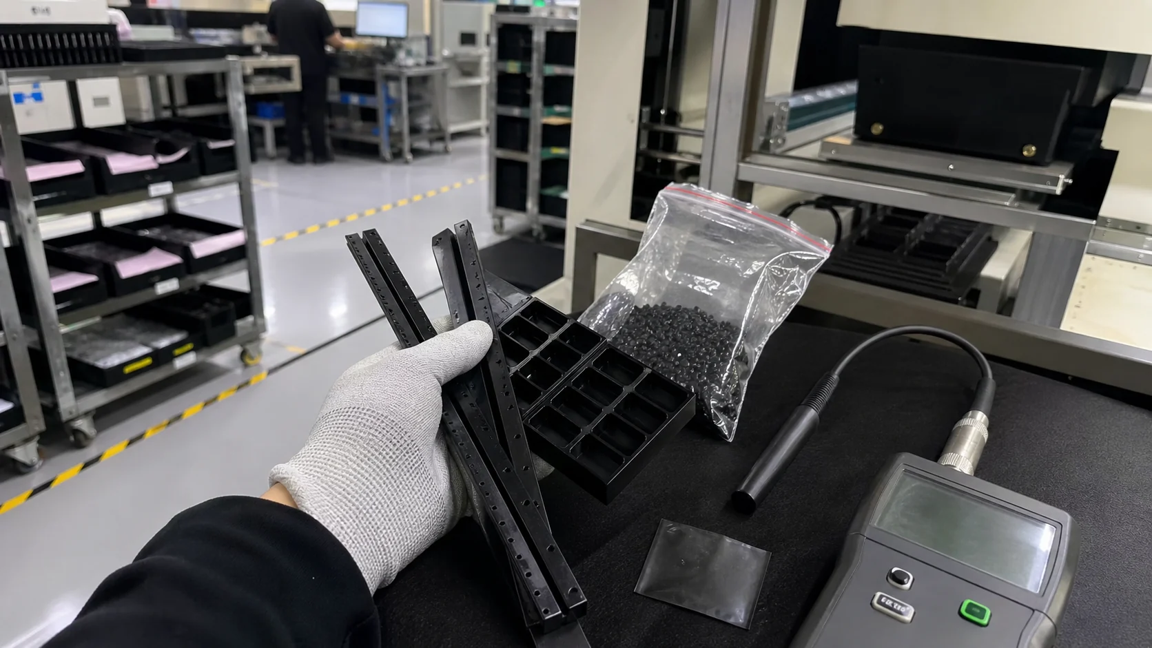
Typical fields include ESD trays, electronic housings, fixtures, EMI parts and antistatic logistics parts. For this article, DEYU would first confirm the working environment, wall thickness, expected lifetime and whether DGK-POM DD4-5ML conductive POM, conductive plastics matches the part geometry or needs formulation adjustment.
What are the main performance indicators for the "conductive plastic" target on POM?
Focus on surface resistance, volume resistance, dispersion uniformity, impact strength and molding stability. Buyers should ask for data on molded parts, not only pellet data, because gate position, filler orientation and thickness can change the final value.
What should engineers watch during injection molding or processing?
For POM, a practical starting window is 180-210°C melt / 70-100°C mold. Avoid excessive filler loading, control weld lines and verify resistance on the molded part. Final parameters should follow part thickness, gate design and the actual machine.
What details help DEYU recommend DGK-POM DD4-5ML conductive POM, conductive plastics more accurately?
Send the current resin or grade, drawing or photo, wall thickness, annual quantity, target standard, failure mode and required color. If a reference grade already passed one test but failed in production, include both data sets.
For a precise recommendation, share the part drawing, base resin, target performance, processing method and test standard with DEYU.
Why conductive POM deserves attention
In electronics handling, semiconductor assembly, battery module production and medical consumable transfer, polymer parts can accumulate static charge during repeated sliding, loading and unloading. Surface antistatic treatments and high carbon-black loading are common routes, but they may lose durability, shed particles, depend on humidity or reduce mechanical strength.
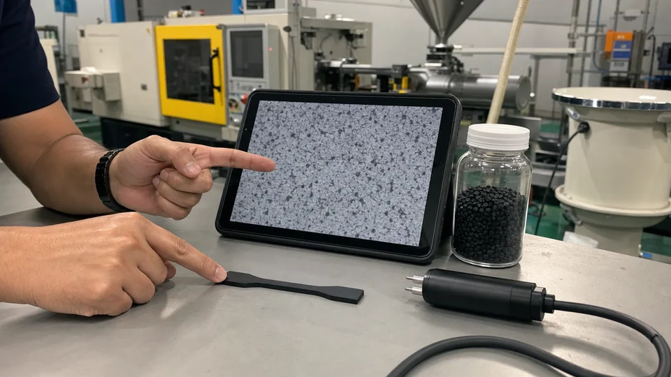
Carbon nanotube modified POM offers another route. POM already provides low friction, wear resistance, creep resistance and dimensional stability. CNTs can build a conductive network at relatively low filler loading, so the material can be considered for precision moving parts that also need ESD control. DEYU's related material direction includes DGK-POM DD4-5ML conductive POM; broader alternatives can be reviewed under conductive plastics.
This guide explains how to evaluate conductive POM: base polymer selection, conductive routes, application fit, processing validation and purchasing documentation.
1. Base polymer selection: why POM is often chosen
For engineering parts that slide, locate, index or run against mating surfaces, POM is often selected before ABS, PP or PA6 because it combines wear resistance, low moisture absorption and stable dimensions. The limitation is electrical: unmodified POM is highly insulating, often around 10^15 ohm surface resistance, so conductivity requires controlled filler dispersion.
| Polymer | Key advantages | Conductive modification difficulty | Typical applications |
|---|---|---|---|
| ABS | Easy processing, low cost, good surface | Conductive fillers can strongly reduce impact strength | Electronics housings, general containers |
| PP | Low density, chemical resistance | Poor filler compatibility and resistance stability can be difficult | Wet-process fixtures, chemical containers |
| PA6 | High strength and heat resistance | Moisture absorption may shift resistance; drying is critical | High-temperature trays, structural brackets |
| POM | Wear resistance, self-lubrication, creep resistance | High crystallinity makes conductive network formation harder | Bushings, guide rails, precision trays |
2. Conductive and antistatic routes
Commercial conductive POM and comparable conductive engineering thermoplastics usually follow four routes. Each route should be judged by resistance range, durability, particle cleanliness and mechanical retention rather than by resistance alone.
| Route | Typical surface resistance | Main advantage | Typical limitation |
|---|---|---|---|
| Surface antistatic agent | 10^7-10^10 ohm | Low cost and little change to the base polymer | Sensitive to wiping, water and humidity |
| Migrating antistatic additive | 10^8-10^11 ohm | Easy to process | Humidity and temperature dependent; may drift over time |
| Carbon black | 10^2-10^5 ohm | Good conductivity and cost control | Mechanical loss and particle-shedding risk |
| Carbon nanotubes | 10^2-10^6 ohm | Low filler loading can form a percolation network and preserve wear performance | Requires high-quality dispersion and batch stability control |
3. CNT-modified POM from DEYU Plast
DEYU Plast uses multi-walled carbon nanotube dispersion technology for conductive POM. The purpose is to form a stable conductive network at lower filler loading while preserving as much of POM's wear resistance and self-lubricating behavior as possible.
For DGK-POM DD4-5ML and related conductive POM directions, the engineering focus is not only the nominal resistance value. Engineers should ask for a TDS, molding guidance, multi-point resistance uniformity data, and resistance stability data after real part processing.
- Conductivity at low filler loading: high-aspect-ratio CNTs support percolation at lower loading than many conventional carbon systems.
- Resistance stability: dispersion quality affects part-to-part and point-to-point surface resistance variation.
- Processing adaptability: POM drying, melt temperature and mold temperature must stay within a controlled window.
4. Application scenarios and selection criteria
SMT fixtures and electronic trays
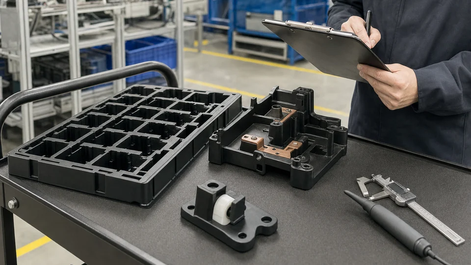
IC trays, PCB tray guides and positioning stops may see repeated insertion and removal, contact with component leads and short exposure to residual reflow heat. Key checks include surface resistance, triboelectric charging tendency, wear after repeated cycles and particle release.
Battery module structural parts
Busbar brackets, insulating spacers and end-plate guides may require dimensional stability, static discharge and chemical compatibility. Validation should include resistance after thermal cycling, volume resistivity after electrolyte or coolant exposure, and tensile strength retention after immersion.
Textile and industrial wear parts
Yarn guide bushings, antistatic sliders and industrial guide elements may work under continuous motion, frictional heat and low humidity. POM's self-lubricating behavior is useful here, but CNT loading and crystallization behavior should be checked through comparative wear testing.
5. Processing validation logic
CNT orientation, shear dispersion and the POM processing window jointly determine final resistance uniformity. A practical validation plan should include drying, injection molding parameters, multi-point resistance mapping and post-machining checks.
| Validation item | Recommended check | Why it matters |
|---|---|---|
| Drying | Typical POM drying around 80-90 C for 3-4 h, depending on grade | Residual moisture can increase thermal degradation and affect surface resistance |
| Processing window | Keep barrel and mold temperatures within supplier guidance | Overheating or poor crystallization may disturb CNT distribution |
| Resistance uniformity | Measure five parts, five points per part; calculate CV | High variation may indicate gate design or molding parameter problems |
| Post-machining | Compare machined and unmachined surfaces | Turning or milling can change the exposed conductive network |
6. Purchasing checklist
Before approving a conductive POM compound, request the following documents and data: TDS with test standards, processing guide, multi-point surface resistance data, batch-to-batch stability report, independent laboratory reports when available, application references, sample testing agreement and a supply-stability statement covering formulation and process changes.
Conclusion
CNT-modified conductive POM is valuable when a part needs both precision motion and ESD control. The right material decision should be based on resistance range, wear behavior, dimensional stability, processing repeatability and application-level validation. For final selection, run trial batches under the actual molding and service conditions rather than relying only on plaque data.