
Conductive or Antistatic Plastic? Defining the Right ESD Resistance Range
A frequent dilemma in plastics engineering: what resistivity range do I actually need? Many buyers and designers use the terms "antistatic" and "conductive" interchangeably, yet they represent fundamentally different performance levels with distinct material formulations, costs, and application fit.
Buyer and engineer FAQ
Questions engineers often ask about this material route
Where can modified plastic with a conductive plastic requirement be used?
Typical fields include ESD trays, electronic housings, fixtures, EMI parts and antistatic logistics parts. For this article, DEYU would first confirm the working environment, wall thickness, expected lifetime and whether DGK-ABS KJD678R-BZ permanent antistatic ABS, DGK-PP DD2-3A conductive PP matches the part geometry or needs formulation adjustment.
What are the main performance indicators for the "conductive plastic" target?
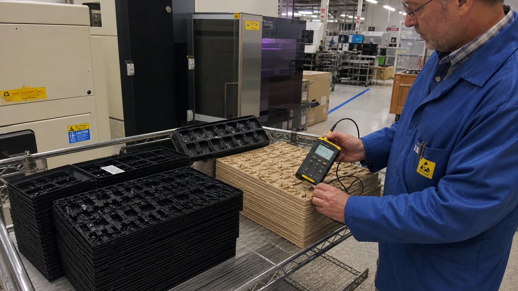
Focus on surface resistance, volume resistance, dispersion uniformity, impact strength and molding stability. Buyers should ask for data on molded parts, not only pellet data, because gate position, filler orientation and thickness can change the final value.
What should engineers watch during injection molding or processing?
Avoid excessive filler loading, control weld lines and verify resistance on the molded part. Start from the base-resin processing window, then adjust by molded-part resistance, appearance and mechanical data.
What details help DEYU recommend DGK-ABS KJD678R-BZ permanent antistatic ABS, DGK-PP DD2-3A conductive PP more accurately?
Send the current resin or grade, drawing or photo, wall thickness, annual quantity, target standard, failure mode and required color. If a reference grade already passed one test but failed in production, include both data sets.
For a precise recommendation, share the part drawing, base resin, target performance, processing method and test standard with DEYU.
Background / Problem
A frequent dilemma in plastics engineering: what resistivity range do I actually need? Many buyers and designers use the terms "antistatic" and "conductive" interchangeably, yet they represent fundamentally different performance levels with distinct material formulations, costs, and application fit.
Related DEYU plastics material references for this selection topic: DGK-ABS KJD678R-BZ permanent antistatic ABS and DGK-PP DD2-3A conductive PP.
The problem manifests in several ways:
Overspecification — specifying conductive materials (resistivity < 10⁴ Ω/sq) for applications that only require static dissipation (10⁴ – 10¹¹ Ω/sq), unnecessarily increasing material cost by 20–50%.
Underspecification — using antistatic grades (10⁹ – 10¹¹ Ω/sq) in environments where rapid charge decay is critical, leading to ESD failures and component damage.
Misinterpretation of data — confusing surface resistivity (measured in Ω/sq) with volume resistivity (Ω·cm), or failing to account for test methods, humidity, and part geometry.
Inconsistent standards — different industries (automotive, electronics, medical, aerospace) use varying definitions and threshold values, making cross-industry selection confusing.
The cost of misselection is tangible: ESD-related damage to electronics costs the global industry an estimated $5–10 billion annually, while unnecessary use of expensive conductive grades inflates material budgets without performance benefit.
Technical Difficulty / Why It Happens
The confusion arises from three interconnected factors:
1. Terminology overlap and inconsistent classification
Different standards bodies and industries define resistivity categories differently:
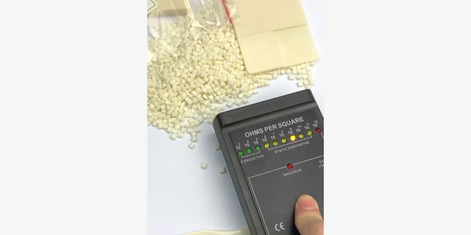
| Category | Surface Resistivity (Ω/sq) — Common Industry Reference | ESDA (ESD Association) Definition | IEC 61340 Definition |
|---|---|---|---|
| Conductive | < 10⁴ | < 10⁴ | ≤ 10⁴ |
| Static Dissipative | 10⁴ – 10¹¹ | 10⁴ – 10¹¹ | > 10⁴ to < 10¹¹ |
| Antistatic | 10⁹ – 10¹² (varies widely) | Not separately defined (often lumped into dissipative) | > 10¹¹ to < 10¹² |
| Insulative | > 10¹¹ | > 10¹¹ | > 10¹² |
The term "antistatic" is especially problematic — it is often used generically for any static-control plastic, yet some suppliers reserve it for materials in the 10⁹–10¹² Ω/sq range, while others apply it to any static-safe material.
2. Test method variability
Surface resistivity depends heavily on measurement conditions:
Electrode geometry — concentric ring vs. parallel bar vs. pin electrodes yield different readings.
Applied voltage — higher voltage may cause breakthrough in thin conductive networks.
Environmental conditions — humidity dramatically affects surface resistivity for many materials (e.g., ionic antistats are humidity-dependent).
Sample preparation — injection molded vs. compression molded; surface contamination; aging effects.
Without standardized testing, two data sheets for nominally the same material may show resistivity ranges differing by an order of magnitude.
3. Application-dependent requirements
The "right" resistivity is not an absolute number — it depends on:
Charge generation rate — how much static electricity is generated in the application.
Sensitivity of components — ESD-sensitive devices have different damage thresholds (e.g., HBM — Human Body Model — sensitivity varies from > 2 kV for robust components to < 100 V for the most sensitive ICs).
Environmental factors — temperature, humidity, presence of flammable gases (where lower resistivity reduces sparking risk).
Required decay time — for ESD-safe packaging, a decay time of < 2 seconds is typical; for grounding applications, near-instantaneous decay is required.
DEYU Material Direction
DEYU approaches resistivity definition and material selection through a structured, application-driven methodology:
Step 1 — Clarify the application context: DEYU engineers work with customers to identify the specific ESD threat — whether it is personnel charging, triboelectric generation during handling, or EMI/RFI shielding. This determines whether conductive (grounding) or static dissipative (controlled decay) behavior is needed.
Step 2 — Define the resistivity target range: Based on the application and component sensitivity, DEYU recommends a specific surface resistivity window. For example:
Gears, bearings, mechanical components — often require 10⁴–10⁶ Ω/sq to prevent sparking while maintaining wear resistance.
Electronic packaging trays and IC carriers — typically specified at 10⁵–10⁹ Ω/sq for balanced ESD protection and dust prevention.
Flooring and work surfaces — often 10⁶–10⁹ Ω/sq for personnel grounding.
Housings and enclosures — often 10⁴–10⁶ Ω/sq to provide both ESD protection and EMI shielding.
Step 3 — Select the appropriate filler system: DEYU matches the resistivity target with the optimal conductive filler route:
Carbon black — provides broad resistivity range (10³–10⁹ Ω/sq) at moderate cost; suitable for static dissipative grades.
Carbon fiber — achieves lower resistivity (10²–10⁶ Ω/sq) with enhanced mechanical reinforcement; ideal for conductive grades requiring structural strength.
Carbon nanotube / graphene — allows precise tuning (10³–10⁹ Ω/sq) at lower loadings, preserving impact resistance and surface finish.
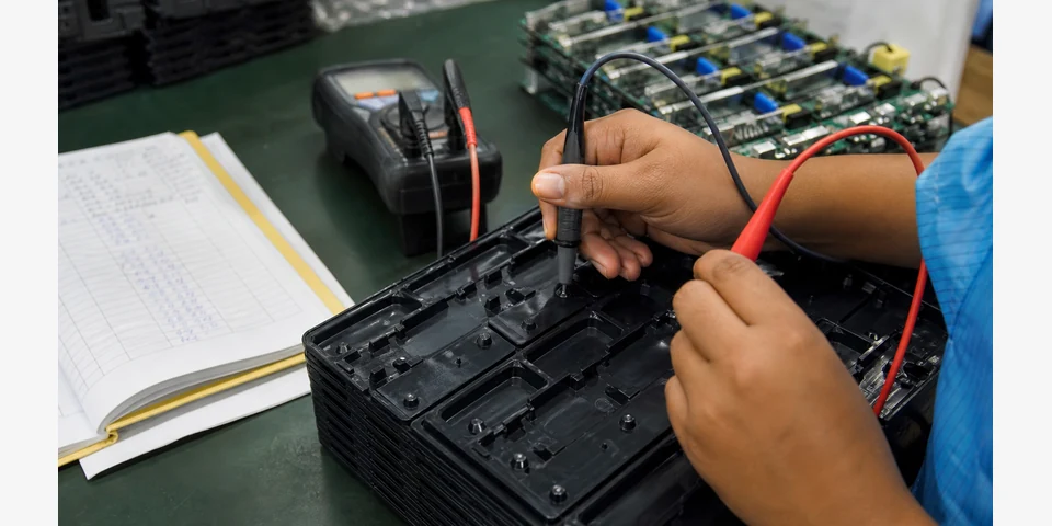
Step 4 — Validate with real part testing: DEYU always recommends small-batch validation using the actual molding and assembly conditions, because laboratory data on standard test bars may not reflect the resistivity distribution in a complex part with weld lines, gate positions, and flow-induced filler orientation.
Reference Product Data — Resistivity Range Selection Matrix
The table below compares typical resistivity ranges and corresponding functional behaviors for DEYU plastics' conductive/antistatic PP-based compounds. All values are directional and subject to formulation-specific adjustment.
| Property | Antistatic Grade (Reference) | Static Dissipative Grade (Reference) | Conductive Grade (Reference) |
|---|---|---|---|
| Base Resin | PP (copolymer) | PP (copolymer) | PP (homopolymer) |
| Modification Route | Ionic antistat / Low-loading carbon black | Carbon black (10–15%) | Carbon fiber (10–20%) |
| Processing Method | Injection molding / extrusion | Injection molding / extrusion | Injection molding |
| Surface Resistivity (Ω/sq) | 10¹⁰ – 10¹² | 10⁵ – 10⁹ | 10² – 10⁴ |
| Volume Resistivity (Ω·cm) | 10¹¹ – 10¹³ | 10⁶ – 10¹⁰ | 10³ – 10⁵ |
| Decay Time (seconds, from 1000V to 100V) | > 2 (humidity-dependent) | < 2 (stable) | < 0.1 |
| Triboelectric Charge (V) | < 100 (at 50% RH) | < 50 (stable) | < 10 |
| Density (g/cm³) | 0.91 – 0.93 | 0.95 – 1.02 | 1.02 – 1.10 |
| MFR (g/10min) | 8 – 20 | 5 – 15 | 5 – 12 |
| Tensile Strength (MPa) | 25 – 30 | 22 – 28 | 30 – 40 |
| Flexural Modulus (MPa) | 1,200 – 1,500 | 1,500 – 2,500 | 3,500 – 5,500 |
| Notched Impact (kJ/m²) | 5 – 8 | 3 – 6 | 2 – 5 |
| HDT @ 1.82 MPa (°C) | 90 – 100 | 90 – 105 | 100 – 115 |
| Typical Applications | Packaging films, low-risk handling trays | IC trays, electronic housing, automotive interior | EMI shielding housings, grounding components |
Customer Debugging / Validation Scenario
Context: An automotive electronics supplier was using a static dissipative PP tray (specified at 10⁶–10⁹ Ω/sq) for handling engine control modules (ECMs). However, they experienced intermittent ESD failures — about 2.3% of modules failed functional testing after handling, with failures traced to electrostatic discharge during transport in low-humidity winter conditions (RH ~25%).
Problem analysis: The existing material’s resistivity shifted upward to > 10¹⁰ Ω/sq under low humidity, because its antistatic mechanism was ionic and humidity-dependent. The decay time increased from < 2 seconds to > 10 seconds, allowing charge accumulation on the tray surface.
Trial structure:
| Parameter | Value |
|---|---|
| Trial Quantity | 1,000 trays (10 injection molding cycles) |
| Monthly Production | 200,000 trays |
| Existing Molding Scrap Rate | 1.5% |
| Existing Assembly/Handling Failure Rate | 2.3% (ESD-related) |
| Target Resistivity | 10⁵ – 10⁹ Ω/sq (stable across humidity) |
DEYU material evaluated: Static dissipative PP compound with carbon black filler (non-ionic, humidity-independent) — a modified version of the DGK-PP series with targeted resistivity of 10⁶–10⁸ Ω/sq.
Validation Data Table (customer internal trial structure):
| Condition | Existing Material (Ionic antistat) | DEYU Material (Carbon black) | Improvement Direction |
|---|---|---|---|
| Surface Resistivity @ 50% RH (Ω/sq) | 5×10⁸ | 8×10⁷ | Stable |
| Surface Resistivity @ 25% RH (Ω/sq) | 2×10¹⁰ | 9×10⁷ | Stable (humidity-independent) |
| Decay Time @ 50% RH (sec) | 1.8 | 0.6 | Faster |
| Decay Time @ 25% RH (sec) | 8.5 | 0.7 | Much faster |
| Triboelectric Charge on tray (V) | 120–250 | 30–50 | Reduced |
| Handling-stage ESD failures (%) | 2.3% | 0.4% | Significantly reduced |
| Molding scrap rate (%) | 1.5% | 1.2% | Slightly improved |
| Assembly pass rate (%) | 97.7% | 99.6% | Improved |
Result Interpretation: The carbon black–filled DEYU compound provided a stable resistivity that remained within the target window regardless of humidity variation. The resistivity shift observed in the ionic antistat material was eliminated. This resulted in consistent decay performance and a fivefold reduction in handling-stage ESD failures. The improved pass rate translated to estimated annual savings of approximately $120,000 in rework and scrap costs.
DEYU plastics' formulation approach prioritized a robust conductive network using carbon black at optimized loading, ensuring the resistivity stayed in the dissipative range without drifting into either insulative or overly conductive territory. The material also maintained good molding stability with slightly reduced scrap rate.
Next steps: Full production validation across multiple molding cavities is recommended. DEYU can support with further resistivity tuning if the application requires a narrower range (e.g., 10⁶–10⁷ Ω/sq) or different mechanical performance.
Result Interpretation — How to Define the Right Resistance Range
Based on the above scenario and broader engineering practice, DEYU recommends the following decision framework:
Step 1 — Identify the primary purpose:
If the goal is grounding / charge elimination / EMI shielding → target resistivity < 10⁴ Ω/sq (conductive)
If the goal is controlled static decay to protect sensitive components → target resistivity 10⁴–10¹⁰ Ω/sq (static dissipative)
If the goal is minimizing dust attraction and preventing nuisance shocks → target resistivity 10⁹–10¹² Ω/sq (antistatic)
Step 2 — Consider the environment:
Low humidity (< 30% RH) → avoid ionic antistats; choose carbon-based or inherently conductive systems
High humidity or wash-down environments → ensure filler system is not leachable
Elevated temperature → verify resistivity stability at operating temperatures
Step 3 — Evaluate part geometry and processing:
Thin-walled or long flow paths → may require higher filler loading to maintain conductivity, but this affects processability; DEYU can adjust viscosity and filler type
Complex geometry with weld lines → resistivity may be higher at weld lines due to filler orientation; validate on actual parts
Painting or plating → some conductive fillers may affect surface adhesion; DEYU offers grades optimized for secondary operations
Step 4 — Balance cost and performance:
Tighter resistivity ranges (e.g., 10⁶–10⁷ Ω/sq) typically require more precise formulation and quality control, adding cost
Wider acceptable range (e.g., 10⁵–10⁹ Ω/sq) allows for more cost-effective production and broader filler selection
Over-specification to conductive grades when dissipative would suffice adds 20–50% material cost for no functional gain
Suitable Applications by Resistivity Range
| Resistivity Range (Ω/sq) | Category | Typical Applications | Recommended DEYU Material Direction |
|---|---|---|---|
| < 10² | Highly Conductive | EMI/RFI shielding gaskets, grounding components, ESD flooring | Carbon fiber or metal-filled compounds |
| 10² – 10⁴ | Conductive | Housings requiring EMI shielding, automotive under-hood ESD parts, spark-proof tooling | Carbon fiber-reinforced PP, ABS, PA66 |
| 10⁴ – 10⁶ | Static Dissipative (low range) | Electronic handling trays, precision component packaging, cleanroom equipment | Carbon black–filled PP or ABS |
| 10⁶ – 10⁹ | Static Dissipative (mid-high range) | IC carriers, medical device housings, instrument panels, conveyor components | Carbon black with controlled loading |
| 10⁹ – 10¹² | Antistatic | Low-risk packaging, films, consumer electronics, dust-free surfaces | Ionic antistats or low-loading carbon black |
| > 10¹² | Insulative | Standard plastics — no ESD functionality | Not applicable (base resin) |
What Buyers Should Provide for Resistance Range Definition
To receive a precise recommendation on the appropriate resistivity range and corresponding material grade, please provide the following:
Application description — what is the part or component used for?
Resistivity requirement — if specified, provide the target range and the test standard used (e.g., ASTM D257, IEC 61340, ESDA S11.11). If not specified, describe the ESD risk.
Environment — typical temperature, humidity range, and any chemical exposure.
Sensitivity of components handled — ESD sensitivity level (e.g., HBM voltage threshold) if known.
Part drawing — geometry, wall thickness, gate location, and flow length.
Processing method — injection molding, extrusion, blow molding, etc.
Current material — if replacing, what is the existing resistivity and performance issue?
Production volume — annual quantity for cost and availability planning.
Secondary operations — painting, plating, laser marking, adhesive bonding — these may affect filler selection.
Regulatory/industry standards — UL94, RoHS, REACH, medical, food contact, or automotive specifications (e.g., GM, Ford, VW).
Conclusion
The distinction between conductive and antistatic plastics is not merely semantic — it is a performance-critical decision that impacts product reliability, manufacturing yield, and material cost. The "right" resistance range is defined by the application’s ESD threat level, environmental conditions, part geometry, and processing constraints.
Key takeaways:
Conductive plastics (ρs < 10⁴ Ω/sq) are for grounding and rapid charge dissipation; they are more expensive and often mechanically reinforced with carbon fiber or metals.
Static dissipative plastics (10⁴–10¹¹ Ω/sq) are the workhorse for ESD-safe handling and packaging; they offer the widest applicability and can be formulated with carbon black for stable, humidity-independent performance.
Antistatic plastics (10⁹–10¹² Ω/sq) are suitable for low-risk applications where only nuisance static reduction is needed; many ionic antistats are humidity-dependent, so carbon-based alternatives are more reliable in variable environments.
DEYU can support the entire selection process — from defining the resistivity target based on application requirements, through formulation optimization with carbon black, carbon fiber, or advanced nanofillers, to small-batch validation and full-scale production. The goal is not to deliver the "best" material, but to deliver the right material for each specific use case, with documented validation data and transparent performance expectations.