Conductive Plastic Compounds: How to Choose Carbon Black, Graphite, Carbon Fiber and Conductive Masterbatch
This page is designed for buyers and engineers who need to select a conductive plastic compound based on real application validation, not only a single resistance value.
Buyer and engineer FAQ
Questions engineers often ask about this material route
Where can ABS / PA66 / PE / POM / PP / TPR / TPU with a conductive plastic requirement be used?
Typical fields include ESD trays, electronic housings, fixtures, EMI parts and antistatic logistics parts. For this article, DEYU would first confirm the working environment, wall thickness, expected lifetime and whether Conductive Plastics, DGK-ABS DD3C Graphite Conductive ABS, Carbon Fiber Reinforced ABS Pellets DGK-ABS CF15L matches the part geometry or needs formulation adjustment.
What are the main performance indicators for the "conductive plastic" target on ABS / PA66 / PE / POM / PP / TPR / TPU?
Focus on surface resistance, volume resistance, dispersion uniformity, impact strength and molding stability. Buyers should ask for data on molded parts, not only pellet data, because gate position, filler orientation and thickness can change the final value.
What should engineers watch during injection molding or processing?
For ABS / PA66 / PE / POM / PP / TPR / TPU, a practical starting window is 210-245°C melt / 50-80°C mold. Avoid excessive filler loading, control weld lines and verify resistance on the molded part. Final parameters should follow part thickness, gate design and the actual machine.
What details help DEYU recommend Conductive Plastics, DGK-ABS DD3C Graphite Conductive ABS, Carbon Fiber Reinforced ABS Pellets DGK-ABS CF15L more accurately?
Send the current resin or grade, drawing or photo, wall thickness, annual quantity, target standard, failure mode and required color. If a reference grade already passed one test but failed in production, include both data sets.
For a precise recommendation, share the part drawing, base resin, target performance, processing method and test standard with DEYU.
This page is designed for buyers and engineers who need to select a conductive plastic compound based on real application validation, not only a single resistance value.
Conductive Plastics and DGK-ABS DD3C Graphite Conductive ABS. Start from the general conductive plastics platform, then narrow the selection by route, base resin and final-part validation.
1. Background / Problem
Conductive plastics are not selected only by checking whether a material can reach a target resistance value. In production, buyers usually need to balance conductivity, injection molding stability, mechanical strength, surface appearance, cost and long-term reliability.
Passing a pellet or standard plaque test does not automatically mean the final molded part will pass. Wall thickness, gate position, filler orientation, cooling rate, drying and service conditions can all change the conductive network.
2. Technical Difficulty / Why It Happens
Conductive modification changes the original behavior of the base resin. Common technical conflicts include:
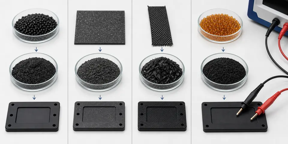
- Carbon black is mature and cost-effective for black conductive PP, PE, ABS and POM parts.
- Graphite can support conductive ABS applications that need stiffness and stable electrical behavior.
- Carbon fiber improves rigidity and conductivity, but shrinkage direction and brittleness must be controlled.
- Conductive masterbatch is useful for early trials and resistance tuning before a final compound is fixed.
For this reason, DEYU treats conductive plastic selection as an application system: base resin, filler route, resistance target, mechanical balance and final-part validation must be matched together.
3. DEYU Material Direction
DEYU may recommend different DGK material directions according to resistance target, base resin and application environment.
| Grade | Base Resin | Corrected Data Direction | Typical Use |
|---|---|---|---|
| DGK-PP DD2-3A | PP | Conductive 10^2-10^3 ohm | Low-resistance PP parts, shielding-related components |
| DGK-PP DD4-5A-JC | PP | V-0; 10^3-10^5 ohm; black | Flame-retardant conductive PP parts |
| DGK-LDPE DD4-5 | PE | Surface resistance around 10^3-10^5 ohm | Molded ESD parts and conductive PE applications |
| DGK-ABS DD3C | ABS | Graphite conductive ABS, around 10^3-10^4 ohm | Conductive ABS housings and ESD cases |
| DGK-ABS CF15L | ABS | Flexural strength >=138 MPa; surface resistance <=10^4 ohm-cm | Rigid carbon-fiber conductive ABS parts |
| DGK-PA66 CF15L-CF40L | PA66 | 15%-40% carbon fiber customizable | High-strength conductive PA66 structural parts |
| DGK-POM DD4-5ML | POM | Conductive 10^4-10^5 ohm; glossy surface and good toughness | Sliding ESD parts and electronic accessories |
| DGK-TPU DD3-4ML | TPU | Conductive 10^4-10^6 ohm; hardness 66 R | Flexible conductive and wear-resistant parts |
| DGK-TPR DD6-9A | TPR | Conductive 10^6-10^9 ohm; hardness 70 | Soft ESD parts and sealing strips |
4. Reference Product Data
The values above are reference values aligned with current DEYU product data. For a final supply decision, exact values should still be confirmed by DEYU internal testing and customer part validation.
5. Real Customer Application Case
In this internal customer case, a customer compares an original material, a previous trial and a DEYU DGK trial direction. The goal is not only lower resistance, but stable molding, surface quality, mechanical balance and part-level pass rate after internal testing.
6. Validation Data Table
| Item | Original Direction | Previous Trial | DEYU Validation Direction |
|---|---|---|---|
| Trial quantity | 500 pcs | 800 pcs | 1,000 pcs |
| Surface resistance before abrasion | 10^8-10^10 ohm | 10^5-10^7 ohm | Target 10^3-10^6 ohm |
| Surface resistance after abrasion | >10^12 ohm | 10^7-10^9 ohm | Target remains in conductive / ESD range |
| Molding scrap rate | 2.5% | 6.8% | Target <4.0% after tuning |
| Dust adhesion | Medium | Low to medium | Low direction |
| Pass rate after internal test | 72% | 81% | Target >90% |
This case is based on a real customer scenario from DEYU's internal project records.
7. Result Interpretation
The key improvement is not simply lowering resistance. A correct conductive compound must keep a stable conductive network after compounding, drying, molding and final use.
For PP and PE, dispersion and flowability are usually critical. For ABS and PA66, stiffness, warpage and assembly cracking must be checked. For POM, TPU and TPR, wear, elasticity and contact behavior should also be evaluated.
8. Suitable Applications
- ESD trays and conductive liners
- Conductive housings and fixtures
- Carbon-fiber reinforced ABS and PA66 structural parts
- Conductive POM sliding components
- Conductive TPU and TPR flexible parts
- Flame-retardant conductive PP components
9. What Buyers Should Provide
To improve validation efficiency, buyers should provide the base resin, target resistance range, test method, part drawing or sample, wall thickness, processing method, color requirement, impact target, warpage requirement, flame-retardant or wear requirement and application environment.
Conclusion
Conductive plastic selection should be validated by matching resin system, conductive route, resistance target, mechanical balance and actual molded part performance. DEYU can support DGK conductive PP, PE, ABS, PA66, POM, TPU and TPR material directions for small-batch validation and application-based adjustment.