
Customer Trial Validation Method for Conductive ABS Molded Components
A conductive ABS compound that passes plaque testing can still fail on a real molded housing. The trial must validate the actual part, not only the material sheet.
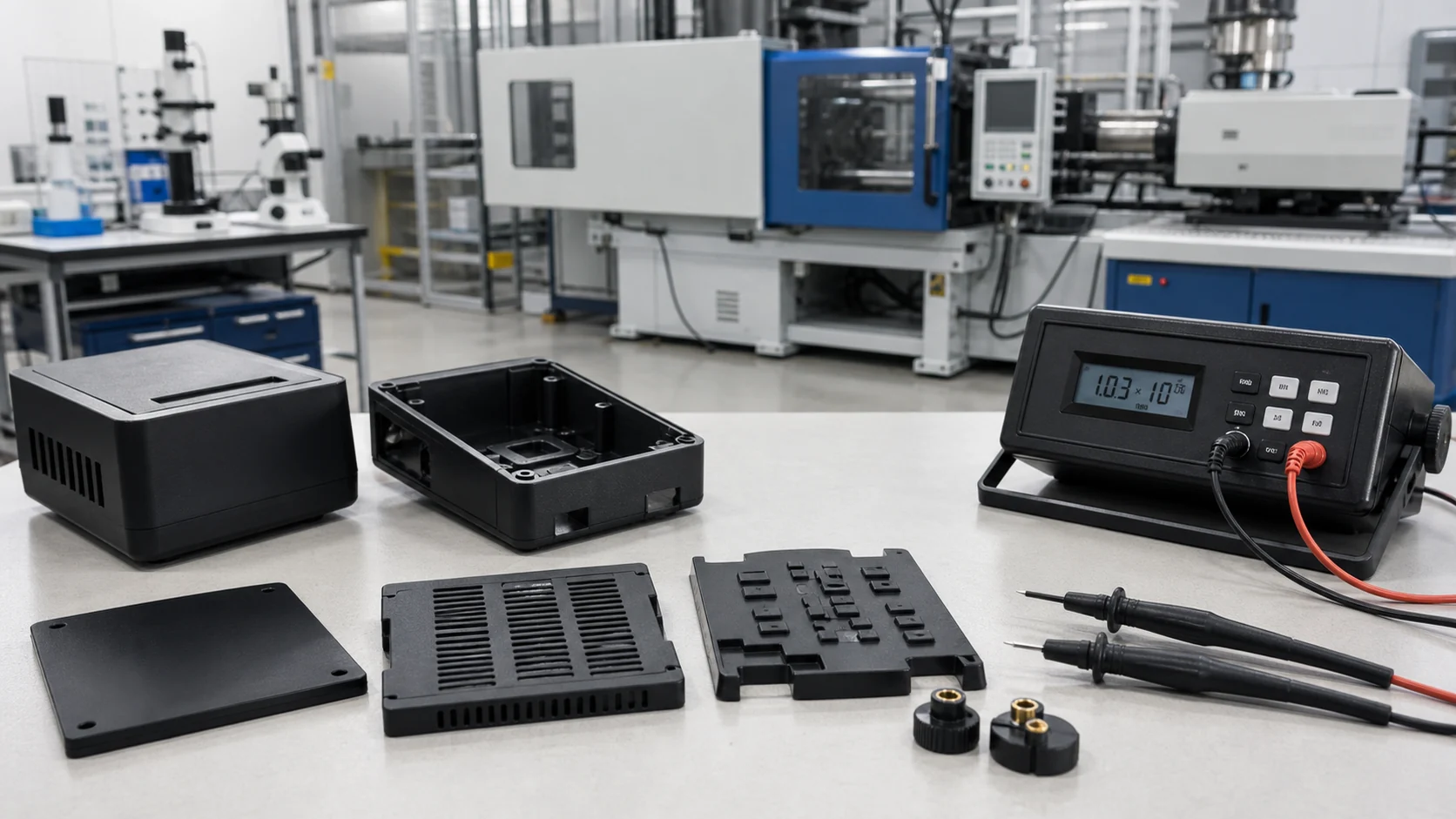
Conductive ABS validation FAQ
Customer Trial Validation Method for Conductive ABS Molded Components
Why is plaque data not enough for conductive ABS qualification?
Conductive fillers orient during injection, and wall thickness, gate location and flow length change the resistance network. A plaque can pass while a thin-wall or flow-end section fails.
How many measurement locations should be used?
Use at least five locations per component: gate, center, flow-end, thin-wall section and corner or edge. Complex parts may need more points.
Which product is most relevant to this validation example?
The closest existing public product page is DGK-ABS KJD678R-BZ. If the final target needs a different resistance range, DEYU can recommend a similar conductive ABS route instead of creating an unnecessary new product page.
What data should be recorded during the trial?
Record molding parameters, conditioning conditions, all resistance readings, mechanical test results, defect categories and scrap rate. Without these records, it is difficult to separate a material issue from a molding or part-design issue.
Background / Problem
When a conductive ABS compound moves from the material data sheet to a production component, the transition is rarely seamless. Engineers routinely encounter a gap between specification and reality: a material that passes laboratory testing on standard plaques may fail on production parts. The same compound that measures 10^4 ohm-cm on a 2 mm plaque may read 10^7 ohm-cm on a thin-wall section of a molded housing.
Product qualification is an essential part of any ESD control plan. Per ANSI/ESD S20.20, qualification testing can be conducted by the organization itself or through independent laboratory evaluation. However, standard material data sheets and plaque tests do not predict the ESD performance of actual injection-molded parts.
The core question is how to design and execute a customer trial validation protocol for conductive ABS molded components that provides reliable, actionable data for qualification decisions. In this example the most relevant existing public material reference is DGK-ABS KJD678R-BZ; if the final requirement is not exactly the same grade, DEYU should select a similar route rather than create a duplicate product page.
Technical Difficulty / Why Conductive ABS Components Require Rigorous Validation
Injection-molded conductive ABS parts are not electrically homogeneous. Several factors create resistivity variation across the part:
Molded plaques may not be sufficiently flat to ensure good electrode contact, and carbon or fiber-loaded polymers are not always homogeneous. Expect some trial time to understand how a conductive ABS compound works in the specific application.
A complete customer trial validation must address electrical performance, mechanical integrity and manufacturing efficiency together.
| Factor | Effect on Resistivity |
|---|---|
| Filler orientation | Conductive fillers align in the flow direction during injection |
| Skin-core structure | The rapidly cooled skin layer often has higher resistivity than the core |
| Gate location | Gate area typically shows the lowest resistivity |
| Flow length | Flow-end areas show the highest resistivity |
| Wall thickness | Thin-wall sections create higher shear, increasing resistivity |
| Dimension | What to Measure | Why It Matters |
|---|---|---|
| Electrical performance | Surface resistivity, volume resistivity, static decay | Verifies ESD protection meets specification |
| Mechanical integrity | Tensile, flexural, impact, dimensional stability | Ensures part survives assembly and service |
| Manufacturing efficiency | Scrap rate, cycle time, defect types | Determines commercial viability |
DEYU Material Direction - Trial Validation Protocol
DEYU recommends a structured four-phase trial validation protocol for conductive ABS molded components. The protocol follows ANSI/ESD S20.20 and ANSI/ESD STM11.11 while adapting to the realities of three-dimensional injection-molded parts.
Phase 1: Pre-Trial Preparation
Define acceptance criteria, prepare equipment and material, then condition samples at 23°C and 12% relative humidity for at least 48 hours before electrical testing.
| Criterion | Typical Requirement | Reference |
|---|---|---|
| Surface resistivity target | <10^6 ohm-sq (conductive) or 10^6-10^9 ohm-sq (dissipative) | Per ESD control program |
| Test method | ANSI/ESD STM11.11 (concentric ring probe) | ESD Association |
| Measurement locations | Minimum 5 locations per component | DEYU recommendation |
| Sample quantity | Minimum 5-10 components per trial batch | DEYU recommendation |
| Mechanical targets | Per part drawing (tensile, flexural, impact) | Customer specification |
| Item | Specification | Source |
|---|---|---|
| Surface resistance meter | Range 10^3-10^12 ohm | ANSI/ESD STM11.11 |
| Concentric ring probe | Per STM11.11 configuration | ESD Association |
| Controlled environment chamber | 23°C, 12% RH | ANSI/ESD STM11.11 |
| Tensile/flexural test equipment | Per ASTM/GB standards | ASTM/GB standards |
| Material | DEYU conductive ABS specified grade | DEYU material confirmation |
Phase 2: Production-Scale Trial Execution
Run the trial under production conditions, not laboratory conditions. Document drying, melt temperature, mold temperature, injection speed, packing pressure, cycle time and defect records.
| Parameter | Typical Range for Conductive ABS | Reference |
|---|---|---|
| Drying temperature | 80-100°C grade-dependent | DEYU datasheet |
| Drying time | 3-4 hours | DEYU datasheet |
| Melt temperature | 220-260°C grade-dependent | DEYU datasheet |
| Mold temperature | 50-90°C grade-dependent | DEYU datasheet |
| Injection speed | Moderate with profile | DEYU recommendation |
| Packing pressure | 40-70 MPa | DEYU recommendation |
| Parameter | Recommendation | Rationale |
|---|---|---|
| Warm-up shots | 20-50 | Stabilize thermal conditions |
| Trial sample quantity | 50-100 components | Sufficient for electrical and mechanical testing |
| Reject tracking | All components | Identify defect types and rates |
Phase 3: Component Testing and Data Collection
Measure surface resistance with a concentric ring probe. Use 10V for conductive materials below 10^6 ohm and 100V for dissipative materials. Use 10-60 seconds electrification time and 3-5 pounds electrode force.
| Location | Why Measure Here |
|---|---|
| Gate area | Typically lowest resistivity - establishes baseline |
| Center of largest flat area | Standard location - comparable to plaque data |
| Flow-end farthest from gate | Highest risk of resistivity drift |
| Thin-wall sections | High shear creates filler orientation - risk area |
| Corners/edges | Stress concentration points - may affect conductivity |
| Test | Method | Typical Targets | Source |
|---|---|---|---|
| Tensile strength | ASTM D638 / GB/T1040 | Per grade datasheet | ASTM D638 / GB/T1040 |
| Flexural modulus | ASTM D790 / GB/T9341 | Per grade datasheet | ASTM D790 / GB/T9341 |
| Impact strength | ASTM D256 / GB/T1843 | Per grade datasheet | ASTM D256 / GB/T1843 |
| Dimensional measurement | CMM or optical | Per part drawing | Part drawing / CMM report |
| Defect Category | Typical Causes | Connection to Material/Process |
|---|---|---|
| Cosmetic rejects | Flow marks, silver streaks, sink marks | Flow instability, moisture, cooling |
| Resistivity failures | Parts exceeding resistivity specification | Filler orientation, shear, dispersion |
| Dimensional failures | Warpage, shrinkage out of tolerance | Cooling, filler orientation |
| Mechanical failures | Cracking, brittleness | Processing-induced degradation |
Phase 4: Data Analysis and Qualification Decision
Analyze each measurement location, cross-part variation, batch consistency and the worst-case location before making the qualification decision.
| Analysis Step | Method | Acceptance Criterion |
|---|---|---|
| All locations | Compare each measurement to target | All must pass specification |
| Cross-part variation | Calculate range max-min | <=1 order of magnitude |
| Batch consistency | Compare across samples | <=1 order of magnitude |
| Worst-case location | Identify highest-resistance location | Must still pass specification |
| Observation | Interpretation | Recommended Action |
|---|---|---|
| All locations pass, variation <1 order | Good filler dispersion; consistent molding | Proceed to production qualification |
| Gate vs. flow-end variation >1 order | Filler orientation along flow path | Optimize gate placement or injection speed |
| Thin-wall sections fail | High shear in thin sections | Increase wall thickness or adjust melt temperature |
| Batch-to-batch variation | Inconsistent material or processing | Verify drying, melt temperature, material consistency |
| Electrical Performance | Mechanical Performance | Scrap Rate | Decision |
|---|---|---|---|
| Pass | Pass | <=5% | Qualify |
| Pass | Pass | 5-10% | Qualify with process optimization |
| Pass | Marginal | Any | Re-evaluate material or redesign |
| Fail | Any | Any | Do not qualify; select alternative |
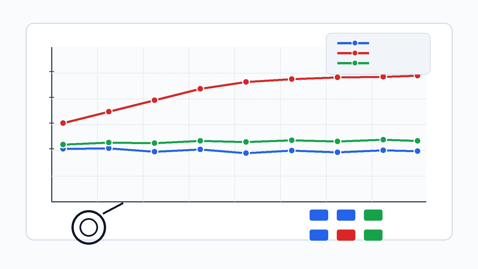
Reference Data - Trial Validation Template
Trial summary form
| Field | Entry |
|---|---|
| Customer name | Electronics manufacturer validation example |
| Component name/number | ESD-safe molded housing |
| Material grade | DGK-ABS KJD678R-BZ |
| Trial date | Customer production-scale trial |
| Trial quantity | 100 housings |
| Processing parameters documented | Yes |
Resistivity measurement log
| Sample ID | Location 1 Gate | Location 2 Center | Location 3 Flow-end | Location 4 Thin-wall | Location 5 Corner | Pass/Fail |
|---|---|---|---|---|---|---|
| 001 initial | 5x10^4 | 8x10^4 | 4x10^5 | 3x10^6 | 6x10^5 | Fail |
| 002 optimized | 5x10^4 | 7x10^4 | 3x10^5 | 5x10^5 | 4x10^5 | Pass |
| Production target | <10^6 | <10^6 | <10^6 | <10^6 | <10^6 | Pass |
Scrap-rate log
| Defect Category | Count | Percentage |
|---|---|---|
| Cosmetic rejects | 2 | 2% |
| Resistivity failures | 1 | 1% |
| Dimensional failures | 1 | 1% |
| Mechanical failures | 0 | 0% |
| Total | 4 | 4% |
Customer Debugging / Validation Scenario
Validation scenario: an electronics manufacturer developed a new ESD-safe housing using DEYU DGK-ABS KJD678R-BZ. The initial trial showed 100% resistivity pass rate on plaques, but production components showed inconsistent results. Approximately 15% of housings failed surface resistivity testing at thin-wall sections.
Root cause: the 1.2 mm thin-wall section created high shear during filling, aligning the carbon black filler and disrupting the conductive network. This is a classic plaque-to-part gap.
Corrective actions increased wall thickness to 1.8 mm, adjusted the injection speed profile and raised melt temperature by 5°C. After optimization, the thin-wall location passed and the qualification decision changed from conditional to qualify.
This scenario shows why production-scale trial validation is essential for conductive ABS components. Plaque data alone did not predict the thin-wall resistivity failure; the structured protocol identified the specific failure location and enabled targeted corrective actions.
Trial protocol
| Parameter | Detail |
|---|---|
| Trial quantity | 100 housings |
| Material | DGK-ABS KJD678R-BZ |
| Processing | Injection molding (production conditions) |
| Drying | 3-4 hours at 80-90?C |
| Melt temperature | 220-240?C |
| Mold temperature | 50-70?C |
| Target surface resistivity | <10^6 ohm-sq |
| Test method | ANSI/ESD STM11.11 |
| Measurement locations | 5 per housing |
Initial trial results
| Location | Range ohm-sq | Mean ohm-sq | Pass/Fail |
|---|---|---|---|
| Gate | 10^4-10^5 | 5x10^4 | Pass |
| Center | 10^4-10^5 | 8x10^4 | Pass |
| Flow-end | 10^5-10^6 | 4x10^5 | Pass |
| Thin-wall | 10^6-10^7 | 3x10^6 | Fail |
| Corner | 10^5-10^6 | 6x10^5 | Pass |
Corrective actions
| Action | Rationale |
|---|---|
| Increased wall thickness from 1.2 mm to 1.8 mm | Reduced shear and filler orientation |
| Adjusted injection speed profile | Reduced shear in thin sections |
| Increased melt temperature by 5°C | Reduced viscosity, improved flow |
Optimized trial results
| Location | Range ohm-sq | Mean ohm-sq | Pass/Fail |
|---|---|---|---|
| Gate | 10^4-10^5 | 5x10^4 | Pass |
| Center | 10^4-10^5 | 7x10^4 | Pass |
| Flow-end | 10^5-10^6 | 3x10^5 | Pass |
| Thin-wall | 10^5-10^6 | 5x10^5 | Pass |
| Corner | 10^5-10^6 | 4x10^5 | Pass |
Final results
| Metric | Initial Trial | Optimized Trial |
|---|---|---|
| Resistivity pass rate | 85% | 99% |
| Total scrap rate | 12% | 4% |
| Qualification decision | Conditional | Qualify |
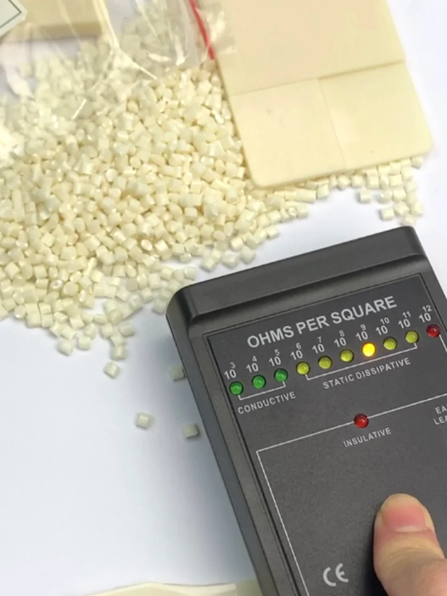
Trial Validation Checklist
Pre-Trial
- Define acceptance criteria; select at least five measurement locations; prepare the surface resistance meter, concentric ring probe and environmental chamber; condition samples per ANSI/ESD STM11.11; document baseline processing parameters.
During Trial
- Run 20-50 warm-up shots; collect 50-100 trial components; record all processing parameters; track rejected parts by defect category; measure surface resistivity at all specified locations; perform mechanical testing if required.
Post-Trial Analysis
- Calculate resistivity pass rate; identify the highest-resistance location; calculate cross-part and batch-to-batch variation; calculate total scrap rate and breakdown; compare results with acceptance criteria; document the qualification decision.
What Buyers Should Provide
- Part drawing or 3D model
- Target surface resistivity range
- Test method such as ANSI/ESD STM11.11, ASTM D257 or GB/T1401-2002
- Proposed measurement locations
- Sample quantity available for the trial
- Current processing parameters
- Current failure mode if any
- Mechanical test requirements
- Monthly or annual production volume
- Regulatory requirements such as ANSI/ESD S20.20 or IEC 61340-5-1
| Information Needed | Why It Matters |
|---|---|
| Part drawing / 3D model | Identifies gate locations, wall thickness variations, flow length - critical for selecting measurement locations |
| Target surface resistivity range | Defines conductive (<10^6) vs. dissipative (10^6-10^9) requirement |
| Test method | ANSI/ESD STM11.11, ASTM D257, GB/T1401-2002, or other |
| Measurement locations | Proposed locations for testing - DEYU can recommend based on part geometry |
| Sample quantity available for trial | Determines statistical significance of results |
| Current processing parameters | Melt temperature, mold temperature, injection speed - baseline for optimization |
| Current failure mode (if any) | Helps focus testing on risk areas |
| Mechanical test requirements | Tensile, flexural, impact - if required for qualification |
| Monthly / annual production volume | Determines commercial viability and scrap rate targets |
| Regulatory requirements | ESD program requirements (ANSI/ESD S20.20, IEC 61340-5-1) |
Conclusion
Customer trial validation of conductive ABS molded components requires a structured, data-driven approach that goes far beyond plaque testing.
DEYU's recommended validation protocol is to define acceptance criteria and measurement locations, prepare equipment, condition materials, execute a production-scale trial, measure surface resistivity at a minimum of five locations, analyze failing points or excessive variation, optimize processing, re-validate and then qualify the component for production.
Validation data from the electronics housing trial demonstrated that the protocol identified a thin-wall resistivity failure missed by plaque testing and enabled corrective actions that improved pass rate from 85% to 99%. For conductive ABS molded components where reliable ESD performance across the entire part is essential, customer trial validation is not optional.
DEYU can provide small-batch validation quantities and trial protocol guidance. Contact DEYU's technical team with part drawings, performance requirements and measurement locations for a customized validation protocol.
| Dimension | Method | Acceptance Criterion |
|---|---|---|
| Electrical performance | Multi-point surface resistivity per ANSI/ESD STM11.11 | All locations pass specification |
| Mechanical integrity | Tensile, flexural, impact testing | Per part drawing requirements |
| Manufacturing efficiency | Scrap rate analysis | <=5% total scrap (target) |