
When Resistance Stability Becomes a Hard Requirement: How DGK Conductive and Antistatic Plastics Keep Batch Uniformity
In semiconductor packaging, SMT handling and battery module assembly, resistance stability is no longer a loose quality claim. It is a part-level and batch-level validation target.
Resistance stability FAQ
When Resistance Stability Becomes a Hard Requirement: How DGK Conductive and Antistatic Plastics Keep Batch Uniformity
What does resistance stability mean in real production?
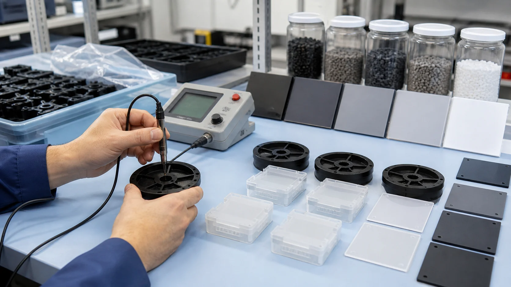
It means the same molded part stays within about 0.5 order across different measurement positions, and consecutive batches remain in the same resistance order instead of jumping by one or two decades.
Why are pellet data not enough?
Gate position, weld lines, shear history, wall thickness and filler orientation can change the final conductive network. Resistance must be mapped on the real part.
Which public product is linked in this article?
The main public reference is DGK-PP KJD789R-A1. Some project notes use KJD789R1 wording, but the public product URL uses KJD789R-A1.
Can all values be treated as public product guarantees?
No. Public product-page values are used only where a public page exists. PC DD5-7A, PC DD5-7JC and POM DD3-4A directions should be treated as project validation directions unless public pages are released.
Why Conductive and Antistatic Plastics Drift
In semiconductor packaging, SMT placement and new-energy battery modules, the static-control ability of a plastic part directly affects yield. A persistent production problem is that the same material, machine and mold can still show resistance differences of one or even two orders of magnitude between positions or between batches.
Typical symptoms include lower resistance near the gate, higher resistance at the flow end, local insulation at weld lines, and an overall rise in resistivity after excessive shear damages the filler structure. These issues are difficult to screen out only by final inspection.
For this article, resistance stability has a concrete engineering meaning: different positions on the same part should generally stay within 0.5 order of magnitude, and consecutive batches should remain locked in the same resistance order.
DGK Technical Logic: Control from Formulation to Process
- Filler orientation under shear. During injection molding and extrusion, conductive fillers orient along the flow direction. The gate area may build a denser conductive path while the far end becomes less connected.
- Network interruption at weld lines. Where two melt fronts meet, conductive fillers may not re-bridge, leaving a locally insulating zone.
- Batch-to-batch formulation and dispersion variation. Changes in filler dispersion or base-resin viscosity can move resistance into a different decade.
Some DGK conductive grades use precisely dispersed carbon nanotube systems instead of simple high-loading carbon black blending. Traditional carbon black PC often needs 16-23% loading to form an effective network, which increases melt viscosity, shear sensitivity and agglomeration risk.
Project directions such as DGK-PC DD5-7A target 10^5-10^7 ohm surface resistivity with a CNT conductive network. DGK-POM DD3-4A project data also show why CNT can be useful in POM: it is less likely than carbon black to bleed to the surface at higher mold temperature, so the mold can be set closer to the crystallization window for a glossy surface.
For antistatic parts, migratory additives and surface coatings usually decay through wiping, migration, humidity loss or depletion. Permanent antistatic routes such as DGK-PP KJD789R-A1 permanent antistatic PP and DGK-ABS KJD890TM use polymeric antistatic systems anchored in the matrix, so performance is less dependent on surface migration.
Representative DGK Grades and Stability Data
DGK-ABS KJD890TM is a transparent permanent antistatic ABS. Public data show surface resistance of 10^9-10^10 ohm and light transmittance above 85%. It is suitable for IC trays, wafer boxes and cleanroom equipment covers where visibility and ESD control are both required. Processing reference: drying 85°C for 4-5 h, injection 195-210°C, mold 70°C.
DGK-PC DD5-7JC is treated here as a custom extrusion-grade conductive PC project direction. It targets 10^5-10^7 ohm surface resistance, HDT 124°C at 0.45 MPa and a no-speck surface. Matte and glossy versions address AOI-sensitive and regular appearance parts.
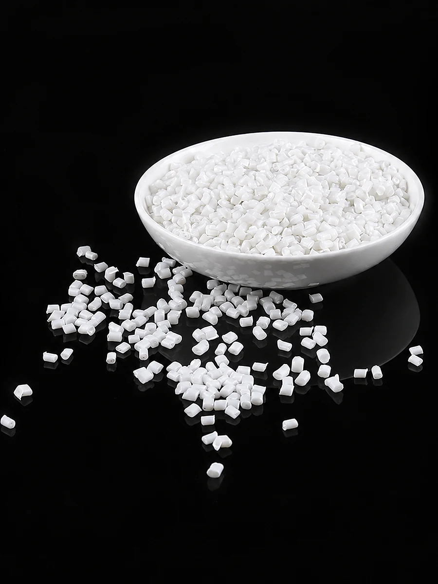
DGK-PP KJD789R1, whose closest public page is DGK-PP KJD789R-A1, is a permanent antistatic PP direction. Project validation recorded resistance staying in the same decade after 48 h at 12% RH and after repeated alcohol wiping. Three-batch verification recorded average values of 3.5x10^9, 4.2x10^9 and 3.8x10^9 ohm, with CV around 18%-22%.
DGK-PP DD2-3A is a CNT composite conductive PP public reference with surface resistivity around 10^2-10^4 ohm for low-resistance molded parts. DGK-POM DD3-4A is treated as a project direction for conductive POM; project data include 10^3-10^4 ohm surface resistivity, tensile yield strength 58 MPa and flexural modulus 2500 MPa.
| Grade | Base | Resistance target | Validation and process notes |
|---|---|---|---|
| DGK-ABS KJD890TM | ABS | 10^9-10^10 ohm | Transparent permanent antistatic ABS. Public page data: light transmittance above 85%; drying 85C/4-5 h, injection 195-210C, mold 70C. |
| DGK-PC DD5-7JC | PC | 10^5-10^7 ohm | Custom extrusion-grade conductive PC direction. HDT 124C at 0.45 MPa; no-speck surface; matte/glossy options; drying 110C/4-5 h, extrusion 255-265C, die 90C. |
| DGK-PP KJD789R1 / KJD789R-A1 | PP | 10^9-10^11 ohm-cm | Permanent antistatic PP direction. Project data: 12% RH for 48 h, 3.8x10^9 to 8.5x10^9; 50 alcohol wipes, 4.1x10^9 to 5.6x10^9; three batches at 3.5x10^9, 4.2x10^9 and 3.8x10^9 ohm, CV 18%-22%. |
| DGK-PP DD2-3A | PP | 10^2-10^4 ohm | Public CNT conductive PP reference for low-resistance molded parts and mature precision-part applications. |
| DGK-POM DD3-4A | POM | 10^3-10^4 ohm | Conductive POM project direction. CNT route; tensile yield 58 MPa, flexural modulus 2500 MPa; glossy surface and better mechanical retention than high carbon-black loading. |
| DGK-PC DD5-7A | PC | 10^5-10^7 ohm | Conductive PC project direction based on precise CNT dispersion for molded parts requiring uniform resistance, low blooming risk and retained toughness. |
Selection by Resistance Range
| Resistance range | Recommended grade | Base resin | Core point |
|---|---|---|---|
| 10^2-10^4 ohm | DGK-PP DD2-3A | PP | CNT composite, low-resistance molded parts |
| 10^3-10^4 ohm | DGK-POM DD3-4A project direction | POM | CNT conductive route, glossy surface and mechanical retention |
| 10^5-10^7 ohm | DGK-PC DD5-7JC project direction | PC | Extrusion sheet, no-speck surface, matte/glossy options |
| 10^5-10^7 ohm | DGK-PC DD5-7A project direction | PC | CNT dispersion for conductive molded parts |
| 10^9-10^10 ohm | DGK-ABS KJD890TM | ABS | Transparent permanent antistatic ABS |
| 10^9-10^11 ohm-cm | DGK-PP KJD789R1 / KJD789R-A1 | PP | Permanent antistatic, natural color, batch CV under project control |
Selection Logic and Validation Advice
- Transparent plus antistatic for IC trays, wafer boxes or cleanroom windows: DGK-ABS KJD890TM.
- Extruded sheet or carrier tape requiring no-speck surface: DGK-PC DD5-7JC project direction.
- Injection molded conductive PC with higher transparency base: DGK-PC DD5-7A project direction.
- Lightweight, permanent antistatic and colorable PP trays or turnover boxes: DGK-PP KJD789R1 / public KJD789R-A1.
- Wear-resistant conductive guide rails, gears or sliders: DGK-POM DD3-4A project direction.
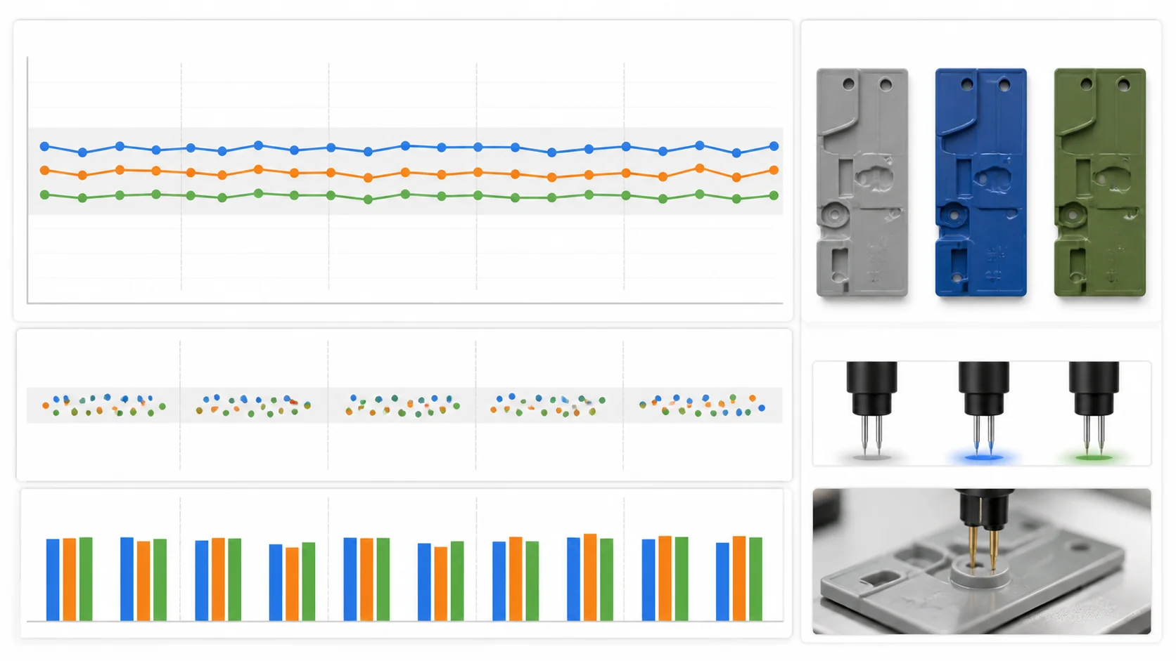
Resistance stability should be validated as a set of measurable indicators: position difference within about 0.5 order, batch CV preferably under 25%, and no decade-level jump after low humidity or repeated wiping. Final grade selection should always be confirmed on real parts because gate design, wall thickness and process window can change the conductive network.