
Graphite-Filled Conductive Plastics: Surface Finish, Stable Resistance and Selection
Among conductive fillers for plastics, graphite occupies a distinct position. Unlike carbon black (which forms conductivity through chain-like aggregates) or carbon fiber (which relies on fiber-to-fiber contact), graphite achieves conductivity through its unique platelet (flake) geometry. Overlapping graphite platelets create conductive pathways through face-to-face contacts, while the layered structure provides inherent lubricity and exceptional thermal conductivity.
Buyer and engineer FAQ
Questions engineers often ask about this material route
Where can modified plastic with a conductive plastic requirement be used?
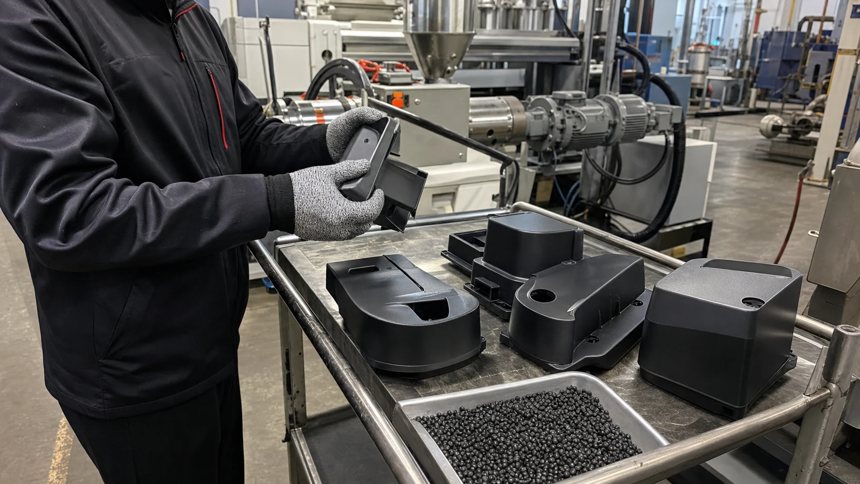
Typical fields include ESD trays, electronic housings, fixtures, EMI parts and antistatic logistics parts. For this article, DEYU would first confirm the working environment, wall thickness, expected lifetime and whether DGK-ABS DD3C graphite conductive ABS, DGK-POM DD4-5ML conductive POM matches the part geometry or needs formulation adjustment.
What are the main performance indicators for the "conductive plastic" target?
Focus on surface resistance, volume resistance, dispersion uniformity, impact strength and molding stability. Buyers should ask for data on molded parts, not only pellet data, because gate position, filler orientation and thickness can change the final value.
What should engineers watch during injection molding or processing?
Avoid excessive filler loading, control weld lines and verify resistance on the molded part. Start from the base-resin processing window, then adjust by molded-part resistance, appearance and mechanical data.
What details help DEYU recommend DGK-ABS DD3C graphite conductive ABS, DGK-POM DD4-5ML conductive POM more accurately?
Send the current resin or grade, drawing or photo, wall thickness, annual quantity, target standard, failure mode and required color. If a reference grade already passed one test but failed in production, include both data sets.
For a precise recommendation, share the part drawing, base resin, target performance, processing method and test standard with DEYU.
Background / Problem
Among conductive fillers for plastics, graphite occupies a distinct position. Unlike carbon black (which forms conductivity through chain-like aggregates) or carbon fiber (which relies on fiber-to-fiber contact), graphite achieves conductivity through its unique platelet (flake) geometry. Overlapping graphite platelets create conductive pathways through face-to-face contacts, while the layered structure provides inherent lubricity and exceptional thermal conductivity.
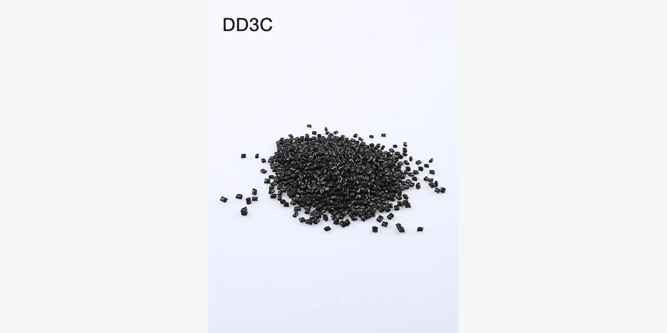
Related DEYU plastics material references for this selection topic: DGK-ABS DD3C graphite conductive ABS and DGK-POM DD4-5ML conductive POM.
The core value proposition of graphite: It delivers conductivity with minimal sacrifice to surface quality — a critical advantage for visible parts, precision components, and applications requiring smooth surfaces. Graphite-filled compounds typically exhibit higher gloss, smoother surfaces, and better surface aesthetics than carbon black or carbon fiber alternatives at equivalent conductivity levels.
The trade-off: Graphite requires higher loadings to achieve the same conductivity as carbon black or carbon fiber, and its mechanical reinforcement is limited compared to carbon fiber. However, for applications where surface quality, stable resistance, and lubricity matter more than absolute conductivity or maximum mechanical strength, graphite is often the optimal choice.
Why graphite matters for surface quality: Carbon black agglomerates can create rough surfaces and visible defects. Carbon fibers can produce fiber “bloom” or surface texture. Graphite platelets, when properly dispersed, lie flat and create a smoother surface finish — making graphite the filler of choice for visible components, cleanroom applications, and parts requiring both conductivity and aesthetic quality.
Graphite also offers exceptional thermal conductivity — reaching values of up to around 30 W/m·K — making it valuable for applications requiring both electrical and thermal management.
Technical Difficulty / How Graphite Creates Conductivity
1. Platelet Geometry and Conductive Network Formation
Graphite consists of layered, flake-shaped particles. Conductive pathways form when overlapping graphite platelets come into face-to-face contact, creating a continuous network through the polymer matrix. Unlike the point-to-point contacts of carbon black aggregates, graphite’s face-to-face contacts provide more stable, less shear-sensitive conductive pathways.
Key geometry parameters:
| Parameter | Effect on Conductivity | Typical Range |
|---|---|---|
| Particle size | Larger particles → lower percolation threshold | 5–150 µm |
| Aspect ratio (diameter/thickness) | Higher aspect ratio → better conductivity | 10–100+ |
| Flake vs. spherical | Flake shape provides better conductivity | Flake preferred |
Flake-shaped graphite produces polymer composites with higher electrical conductivity than those containing sphere-shaped graphite. The platelet geometry creates more contact area between adjacent particles, reducing contact resistance and improving network stability.
2. The Percolation Threshold
The percolation threshold for graphite-filled composites varies significantly based on filler type, particle size, and dispersion quality. Research shows:
| Graphite Type | Percolation Threshold | Reference |
|---|---|---|
| Natural graphite in PET | ~13.2 wt% | Conductivity rises from 0.00347 S/m at 10 wt% to 6.97 S/m at 30 wt% |
| Untreated graphite in epoxy | 15–17 vol% | Higher threshold due to lower aspect ratio |
| Expanded graphite in epoxy | 2.8–8.5 vol% | Lower threshold due to high aspect ratio |
| Expanded graphite in nanocomposites | 5–6 vol% | Significantly lower than untreated graphite |
Expanded graphite (thermally expanded graphite) forms continuous networks within polymer matrices, resulting in improved electrical and thermal conductivity at lower loadings. The high aspect ratio of expanded graphite sheets enables percolation at much lower concentrations.
3. Conduction Mechanism — Tunneling and Contact
Above the percolation threshold, conduction in graphite-polymer composites is dominated by thermally activated tunneling between adjacent graphite platelets. The platelet geometry creates multiple contact points, providing redundancy in the conductive network and making resistivity less sensitive to mechanical deformation or thermal cycling.
4. Temperature Stability of Resistivity
Graphite-filled composites exhibit relatively stable resistivity across temperature variations. Studies show that above the percolation threshold, changes in resistivity with temperature are weak. This temperature stability makes graphite an attractive option for applications exposed to thermal cycling or varying operating temperatures — where resistance drift could otherwise cause ESD failures.
5. The Lubricity Advantage
Graphite’s layered structure provides intrinsic lubricity. In sliding contact applications — gears, bearings, sliding guides — graphite reduces friction and wear while providing conductivity. This dual functionality (conductivity + wear resistance) is unique among conductive fillers and makes graphite the material of choice for moving conductive components.
DEYU Material Direction — Graphite Compounding Approach
DEYU approaches graphite conductive compounding through a systematic methodology focused on surface quality and resistance stability:
1. Graphite Grade Selection Based on Application
| Graphite Type | Key Characteristics | Best Suited For |
|---|---|---|
| Natural flake graphite | Good conductivity, cost-effective | General conductive applications |
| Expanded graphite | Lower percolation threshold, higher conductivity | High-performance, low-loading applications |
| Synthetic graphite | Consistent quality, controlled particle size | Precision applications |
| Micro/nano-graphite blends | Surface quality + conductivity | Smooth surface, visible parts |
Micro- and nano-graphite blends can create multistage structures that provide both conductivity and surface quality. With a 1:1 ratio of micro- and nano-graphite, coatings exhibit minimal resistance while maintaining stable conductivity even under challenging conditions.
2. Dispersion Quality — The Key to Surface Quality
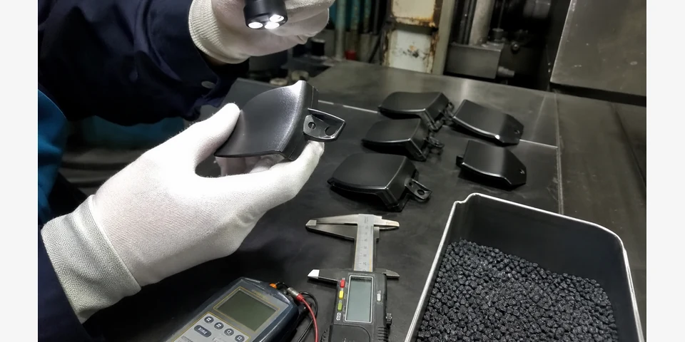
Poor graphite dispersion creates agglomerates that appear as surface defects and reduce conductivity. DEYU ensures:
Optimal compounding shear to exfoliate graphite into thin platelets
Compatibilizers or surface treatments to improve polymer-filler interaction
Controlled mixing time and temperature to prevent platelet damage
Dispersion verification through microscopy and resistivity mapping
3. Loading Optimization — Balancing Conductivity and Properties
DEYU determines the minimum graphite loading required to achieve target resistivity while preserving:
Surface quality (smoothness, gloss)
Mechanical properties (impact strength, flexibility)
Processability (flow, mold filling)
Cost-effectiveness
4. Synergistic Hybrid Systems
Graphite can be combined with other fillers for enhanced performance. Research shows that hybrid systems containing graphite and carbon black can achieve significantly lower resistivity than either filler alone — the hybrid system containing 30 wt% large graphite particles and 15 wt% carbon black exhibited resistivity of 0.027 Ω·cm, compared to 0.406 Ω·cm for 45 wt% carbon black alone. This synergistic effect enables lower total filler loading while achieving superior conductivity.
Reference Product Data — Graphite Conductive Compounds
The table below provides reference data for graphite-filled conductive compounds across different base resins. All values are directional.
| Property | DGK-ABS-G (General) | DGK-POM-G (Wear) | DGK-PP-G (Cost-Effective) | DGK-PC-G (Surface Quality) |
|---|---|---|---|---|
| Base Resin | ABS | POM | PP | PC |
| Graphite Loading | 15–25% | 12–20% | 20–30% | 15–25% |
| Processing Method | Injection molding | Injection molding | Injection molding, extrusion | Injection molding |
| Surface Resistivity (Ω/sq) | 10³ – 10⁵ | 10⁴ – 10⁶ | 10⁵ – 10⁸ | 10³ – 10⁵ |
| Volume Resistivity (Ω·cm) | 10³ – 10⁵ | 10⁴ – 10⁶ | 10⁵ – 10⁸ | 10³ – 10⁵ |
| Surface Gloss (60°) | 35–50 | 25–40 | 20–35 | 40–60 |
| Surface Roughness (Ra, µm) | 0.3–0.6 | 0.4–0.8 | 0.5–1.0 | 0.2–0.5 |
| Thermal Conductivity (W/m·K) | 5–15 | 5–15 | 5–20 | 5–15 |
| Density (g/cm³) | 1.15–1.25 | 1.45–1.55 | 1.05–1.15 | 1.25–1.40 |
| MFR (g/10min) | 5–15 | 4–12 | 3–10 | 5–15 |
| Tensile Strength (MPa) | 35–50 | 50–65 | 22–28 | 50–65 |
| Flexural Modulus (MPa) | 4,000–6,000 | 4,500–6,500 | 1,500–2,500 | 5,000–7,000 |
| Notched Impact (kJ/m²) | 4–8 | 4–6 | 3–5 | 5–8 |
| Coefficient of Friction | Low-Moderate | Very Low | Moderate | Low-Moderate |
| HDT @ 1.82 MPa (°C) | 85–100 | 100–120 | 95–110 | 120–140 |
| Typical Applications | Electronic housings, visible parts | Gears, bearings, sliding guides | ESD trays, packaging | Premium housings, displays |
Customer Debugging / Validation Scenario
Context: A manufacturer of premium electronic display housings was using a carbon black-filled ABS compound for ESD protection. The material met resistivity requirements (10⁶–10⁸ Ω/sq) but was causing two problems: (1) surface quality issues — the carbon black created visible surface defects and reduced gloss below the customer’s aesthetic standard, and (2) inconsistent resistivity at elevated temperatures — the housing was used in applications with moderate temperature variation (20–60°C), and resistivity drifted by nearly an order of magnitude, causing intermittent ESD failures.
Problem analysis:
| Issue | Root Cause | Impact |
|---|---|---|
| Surface defects | Carbon black agglomerates created rough texture | 12% aesthetic reject rate |
| Gloss too low | Carbon black loading (15%) reduced surface gloss | Failed customer specification (gloss < 40 at 60°) |
| Resistivity drift with temperature | Carbon black network sensitive to thermal expansion | Resistivity: 10⁷ Ω/sq at 20°C → 10⁸ Ω/sq at 60°C |
Trial structure:
| Parameter | Value |
|---|---|
| Trial Quantity | 500 housings (5 molding cycles) |
| Monthly Production | 100,000 housings |
| Existing Aesthetic Reject Rate | 12% |
| Target Surface Resistivity | 10⁶ – 10⁸ Ω/sq (stable across 20–60°C) |
| Target Surface Gloss (60°) | > 45 |
DEYU interventions:
Filler change — switched from carbon black to graphite-filled ABS (DGK-ABS-G)
Graphite grade optimization — selected fine flake graphite with controlled particle size for improved surface quality
Dispersion optimization — adjusted compounding parameters for uniform platelet distribution
Loading optimization — optimized graphite loading (20%) to achieve target resistivity with minimal impact on surface quality
Validation Data Table (customer internal trial structure):
| Parameter | Existing Material (CB-ABS) | DEYU Material (DGK-ABS-G) | Improvement Direction |
|---|---|---|---|
| Surface Resistivity @ 20°C (Ω/sq) | 5×10⁷ | 3×10⁷ | Stable |
| Surface Resistivity @ 60°C (Ω/sq) | 8×10⁸ | 4×10⁷ | Stable (no drift) |
| Resistivity Drift (20°C → 60°C) | 16× increase | 1.3× increase | Eliminated |
| Surface Gloss (60°) | 32 | 52 | Improved |
| Surface Roughness (Ra, µm) | 0.8 | 0.35 | Improved |
| Aesthetic Reject Rate | 12% | 2.5% | Reduced |
| Molding Scrap Rate | 5% | 3.5% | Reduced |
| Overall Pass Rate | 83% | 94% | Improved |
Result Interpretation:
Existing material analysis: The carbon black-filled ABS achieved the target resistivity but at significant cost to surface quality. Carbon black agglomerates created visible surface defects and reduced gloss. The resistivity drift with temperature was caused by thermal expansion disrupting the carbon black network — the point-to-point contacts between carbon black aggregates were sensitive to temperature-induced volume changes.
DEYU graphite solution: The graphite-filled ABS (DGK-ABS-G) delivered stable resistivity across the temperature range. The platelet geometry of graphite creates face-to-face contacts that are less sensitive to thermal expansion than the point-to-point contacts of carbon black. The fine flake graphite, when properly dispersed, lies flat on the surface, creating a smoother finish with higher gloss.
DEYU plastics' contribution: DEYU provided a comprehensive solution addressing both surface quality and resistivity stability: (1) selection of fine flake graphite grade optimized for surface quality, (2) optimized dispersion to eliminate agglomerates and maximize platelet alignment, and (3) loading optimization to achieve target resistivity while preserving surface aesthetics.
Next steps: Full production validation across all housing variants. DEYU can provide ongoing technical support and in-process surface quality monitoring protocols.
Result Interpretation — Graphite Selection Framework
Based on the analysis and scenario above, DEYU recommends the following framework for graphite conductive compound selection:
Step 1 — Define the application priority:
| Priority | Recommended Approach | Why Graphite |
|---|---|---|
| Surface quality critical | Fine flake graphite, optimized dispersion | Platelets lie flat, creating smooth surfaces |
| Resistivity stability critical | Expanded or high-aspect-ratio graphite | Face-to-face contacts resist thermal disruption |
| Wear resistance + conductivity | Graphite in POM or PA | Lubricity reduces friction while providing conductivity |
| Thermal management + conductivity | Graphite in any base resin | Graphite provides exceptional thermal conductivity (up to 30 W/m·K) |
| Cost-sensitive conductivity | Graphite in PP or PE | Lower cost than carbon fiber, competitive with carbon black |
Step 2 — Select graphite type based on requirements:
| Requirement | Recommended Graphite Type |
|---|---|
| Surface quality, visible parts | Fine flake graphite (< 20 µm) |
| High conductivity, low loading | Expanded graphite |
| Consistent quality, precision | Synthetic graphite |
| Lubricity + conductivity | Natural flake graphite |
Step 3 — Optimize loading:
Start at the minimum loading that achieves target resistivity
For surface-critical applications, use finer graphite grades at slightly higher loadings
For wear applications, balance graphite loading with wear additive requirements
Consider hybrid systems (graphite + carbon black) for synergistic conductivity improvement
Step 4 — Ensure good dispersion:
Use adequate compounding shear to exfoliate graphite into thin platelets
Consider surface treatments to improve polymer-filler interaction
Verify dispersion quality through microscopy and surface roughness measurement
Step 5 — Validate surface quality and resistivity stability:
Measure surface gloss (60°) and roughness (Ra) on production parts
Test resistivity at operating temperature extremes
Validate surface appearance against customer specifications
Advantages of Graphite Conductive Plastics
| Advantage | Explanation |
|---|---|
| Superior surface quality | Platelet geometry creates smoother surfaces than carbon black or carbon fiber |
| Stable resistivity | Face-to-face contacts are less sensitive to thermal and mechanical stress |
| Lubricity | Graphite’s layered structure reduces friction and wear in moving parts |
| High thermal conductivity | Up to 30 W/m·K — superior to carbon black and most other carbon fillers |
| Good chemical stability | Graphite is inert and compatible with most polymer systems |
| Low density | Lower density than metal-based conductive fillers |
| Cost-effective | Less expensive than carbon fiber or CNT, competitive with carbon black |
| Permanent conductivity | Does not migrate or wash out (unlike ionic antistats) |
| Humidity-independent | Conductivity is not affected by humidity changes |
| Process flexibility | Suitable for injection molding, extrusion, and compression molding |
Limitations of Graphite Conductive Plastics
| Limitation | Explanation | Mitigation |
|---|---|---|
| Higher loading required | Typically 15–30% loading for target conductivity, higher than carbon black or CNT | Use expanded graphite or hybrid systems to reduce loading |
| Limited mechanical reinforcement | Graphite does not provide the same strength enhancement as carbon fiber | Consider hybrid systems (graphite + carbon fiber) for structural applications |
| Brittleness at high loadings | High graphite loadings can reduce impact strength | Use impact modifiers; optimize loading |
| Porosity at very high loadings | High graphite content can create porosity | Balance loading with processing optimization |
| Anisotropic properties | Conductivity may vary with filler orientation | Consider part geometry and flow direction |
| Dispersion challenges | Graphite can be difficult to disperse uniformly | Use surface treatments; optimize compounding |
| Dark color only | Graphite produces dark gray to black color | Color options limited; consider coatings for color requirements |
Suitable Applications — Graphite Conductive Plastics
| Application | Recommended Base Resin | Why Graphite |
|---|---|---|
| Electronic housings (visible) | ABS, PC | Surface quality, stable resistivity |
| Gears, bearings, sliding guides | POM | Lubricity + conductivity + wear resistance |
| Cleanroom fixtures | ABS, PC | Low particle generation, smooth surface |
| EMI shielding enclosures | ABS, PC, PA | Conductivity + surface quality |
| Thermal management components | PP, PA, PC | High thermal conductivity + electrical conductivity |
| Automotive interior ESD parts | PP, ABS | Surface quality + static dissipation |
| Precision mechanical components | POM | Dimensional stability + lubricity + conductivity |
| Conductive rollers, wheels | TPU, PP | Surface quality + wear resistance |
| Medical device housings | PC, ABS | Smooth surface, stable resistivity, biocompatibility |
| Display housings, premium electronics | PC, ABS | Surface aesthetics + ESD protection |
What Buyers Should Provide for Graphite Compound Selection
To receive a precise graphite compound recommendation, buyers should provide:
Target resistivity — surface or volume resistivity range (Ω/sq or Ω·cm) with test standard
Surface quality requirements — gloss target, roughness limit, visible defect tolerance
Application description — what is the part and what does it do?
Part drawing — geometry, wall thickness, gate location, critical surfaces
Processing method — injection molding, extrusion, compression molding
Mechanical requirements — tensile strength, impact strength, wear resistance
Thermal requirements — continuous use temperature, thermal cycling range
Lubricity/wear requirements — if the part involves sliding contact
Environmental conditions — temperature range, chemical exposure, humidity
Production volume — annual or monthly quantity
Color requirements — dark gray/black acceptable, or lighter color needed?
DEYU can support with:
Graphite grade selection based on surface quality and conductivity requirements
Loading optimization for target resistivity with property preservation
Dispersion optimization for consistent surface quality
Hybrid system development (graphite + carbon black or graphite + carbon fiber)
Small-batch validation and process optimization support
Conclusion
Graphite occupies a unique position among conductive fillers for plastics. While it requires higher loadings than carbon black or carbon fiber to achieve equivalent conductivity, it delivers distinct advantages that make it the optimal choice for many applications.
Key takeaways:
Surface quality is graphite’s greatest advantage — platelet geometry creates smoother surfaces with higher gloss than carbon black or carbon fiber alternatives
Resistivity stability — face-to-face platelet contacts are less sensitive to thermal and mechanical stress than the point-to-point contacts of carbon black, providing stable resistivity across temperature variations
Lubricity — graphite’s layered structure reduces friction and wear, making it the filler of choice for moving conductive components (gears, bearings, sliding guides)
Thermal conductivity — graphite provides exceptional thermal conductivity (up to 30 W/m·K), valuable for applications requiring both electrical and thermal management
Hybrid systems offer synergy — combining graphite with carbon black can achieve significantly lower resistivity than either filler alone, enabling lower total loading and better property balance
Not for every application — for applications requiring maximum mechanical reinforcement or lowest possible loading, carbon fiber or CNT may be more appropriate
DEYU offers a full range of graphite conductive compounds across ABS, POM, PP, PC, and other base resins — with optimized loadings, dispersion control, and surface quality assurance for applications where appearance and stable performance matter.