Transparent Antistatic Plastic for Packaging Boxes: Injection Molding Process and Key Points
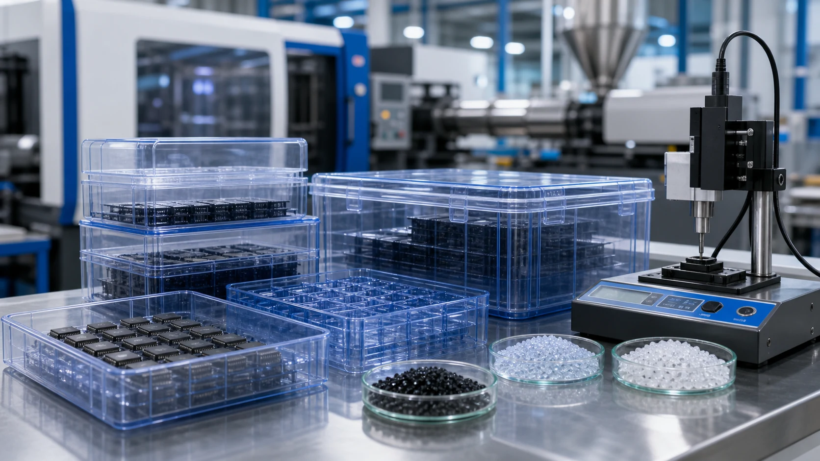
DGK-ABS KJD890TM is a transparent antistatic ABS for IC trays, wafer boxes, electronic circulation boxes and medical packaging. It keeps about 85% transmittance at 2 mm, stable 10^8-10^10 ?/sq surface resistivity and high flow for thin-wall injection molding. This guide summarizes drying, temperature, mold design, defect control and validation.
Buyer and engineer FAQ
Questions engineers often ask about transparent antistatic packaging boxes
Where can DGK-ABS KJD890TM transparent antistatic ABS packaging boxes be used?
It is suitable for IC trays, wafer packaging boxes, electronic component circulation boxes, medical consumable packaging, clear protective covers and premium transparent packaging where visual inspection and 10^8-10^10 Ω·sq static-dissipative behavior are both required.
What molding temperature should be used for this transparent antistatic ABS?
A practical starting setting is 185/195/205°C for rear/middle/front barrel, about 200°C nozzle and 60-80°C mold. For thin walls below 1.5 mm, the front zone may be raised toward 210°C, but the melt should preferably stay below 220°C.
Why do transparent antistatic boxes show white haze or silver streaks?
The first checks are moisture and overheating. Dry at 85°C for 4-5 hours to reach below 0.05% moisture, then check whether barrel or nozzle temperature is too high or whether retained melt is degrading in a dead corner.
How should the mold be designed for stable surface resistance?
Use a smooth, balanced runner system, enlarge runner area by 10%-15%, avoid high-shear pin gates on visible areas, vent flow ends at 0.02-0.03 mm and keep mold temperature variation within 5°C so the antistatic phase is distributed more evenly.
For a precise recommendation, share the part drawing, wall thickness, gate design, target resistance, transparency target and molding method with DEYU.
1. Material selection and pretreatment
1.1 How material properties affect packaging-box molding
For a transparent antistatic packaging box, material selection is the first condition for a stable project. The molded box usually needs a clear appearance, reliable ESD control, enough impact resistance for daily handling, and enough flow to fill ribs, buckles, thin walls and long flow paths without excessive shear. DGK-ABS KJD890TM is designed for this balance: it keeps the transparency required for inspection while using a permanent antistatic route rather than a temporary surface coating.
| Property | Test standard | Typical value | Effect on packaging-box molding |
|---|---|---|---|
| Light transmittance (2 mm) | ASTM D1003 | ~85% | Supports visual inspection and AOI recognition. |
| Surface resistivity | GB/T 1401 / IEC 61340-5-1 | 10^8-10^10 Ω·sq | Permanent antistatic behavior, not easily lost after wiping or washing. |
| Melt flow rate (220°C/10kg) | GB/T 3682 | 46.4 g/10min | High flow for thin-wall filling and long-flow cavities. |
| Notched Izod impact strength (23°C) | GB/T 1843 | 12.3 kJ/m² | Helps the box resist normal handling impact. |
| Heat deflection temperature (0.45 MPa) | GB/T 1633 | 85°C | Suitable for ordinary use, storage and transport temperature ranges. |
| Density | GB/T 1033 | 1.118 g/cm³ | Supports lightweight molded packaging parts. |
For electronic component trays and similar thin-wall packaging boxes, a wall thickness of 1.0-1.5 mm is common. In this thickness range, a high-flow material with MFI above 40 is important for complete filling, especially when the part has ribs, small positioning steps or long flow distance. For medical consumable boxes or premium consumer packaging, buyers should also discuss low volatility, odor, cleanliness and sanitation requirements before confirming the grade.
1.2 Drying: the first process gate for transparent antistatic ABS
Transparent antistatic ABS is moisture sensitive. If the pellets contain too much water, moisture vaporizes during injection and creates silver streaks, bubbles or cloudy marks on the surface. These defects damage both transparency and the premium appearance of the packaging box.
- Recommended drying temperature: 85°C. For ABS-based materials, 80-90°C is the normal practical range.
- Recommended drying time: 4-5 hours. At least 2-3 hours should be secured for small trials, but stable mass production should use the longer window.
- Recommended equipment: a dehumidifying dryer is preferred. Ordinary hot-air drying can introduce airborne moisture or contamination.
- Moisture target: below 0.05% before molding.
A frequent production mistake is drying for less than 2 hours or drying below 80°C. In that case, residual water often appears as silver streaks, white haze or small bubbles after molding. Dried pellets should be kept sealed or supplied by a closed conveying system to avoid re-absorption of moisture before they enter the hopper.
2. Injection molding process parameter control
2.1 Injection temperature: balancing flow and thermal stability
The injection temperature of transparent antistatic ABS directly affects transparency, color tone and antistatic stability. If the temperature is too high, the antistatic system may suffer thermal oxidation or decomposition, causing haze increase or yellowing. If the temperature is too low, the material may not fill thin walls or long-flow sections completely.
- Barrel temperature, rear / middle / front: 185 / 195 / 205°C.
- Nozzle temperature: about 200°C.
- Melt temperature upper limit: preferably not above 220°C to reduce thermal oxidation of the antistatic system.
Use staged temperature control and let the barrel rise gradually from rear to front so that the melt plasticizes uniformly. The nozzle should not be overheated, because retained melt at the nozzle can degrade and later appear as yellow marks or cloudy streaks. For thin-wall boxes below 1.5 mm, the front zone may be raised moderately to about 210°C when filling is difficult, but the residence time should still be controlled.
2.2 Mold temperature: surface quality, internal stress and dimensional stability
Mold temperature strongly affects gloss, internal stress and dimensional stability in transparent antistatic molded parts. A mold that is too cold freezes the melt too quickly and leaves insufficient surface replication; a mold that is too hot lengthens cycle time and can reduce production efficiency.
- Recommended mold temperature: 60-80°C.
- If mold temperature is below 50°C, surface gloss may be poor, internal stress can rise and warpage risk increases.
- If mold temperature is above 80°C, the cycle becomes longer and the release rhythm may slow down.
- For high-precision IC trays, 50-60°C is often used as a stable starting point. For high-gloss packaging boxes, 60-80°C is more suitable.
- Cooling channels should be balanced. A practical reference is 80-120 mm between water channels and 15-25 mm from the cavity surface.
2.3 Injection pressure, speed and back pressure
Injection pressure and speed should be tuned according to part wall thickness, rib density, flow length and gate location. Transparent antistatic ABS should fill smoothly without excessive jetting, trapped air or over-shearing of the antistatic phase.
- Injection pressure: normally 750-1200 bar. Thin-wall boxes use the upper part of the range; thicker boxes can be lower.
- Injection speed: use a multi-stage profile. Start slowly near the gate to avoid jetting, fill the main cavity quickly to reduce weld-line severity, then slow down for packing to reduce internal stress.
- Back pressure: 3-5 bar. This supports uniform plasticizing while avoiding unnecessary shear heat.
2.4 Recommended process window summary
| Process item | DGK-ABS KJD890TM reference value | Control point |
|---|---|---|
| Drying temperature | 85°C | 4-5 hours, dehumidifying dryer preferred. |
| Barrel temperature, rear / middle / front | 185 / 195 / 205°C | Gradual rise from rear to front. |
| Nozzle temperature | 200°C | Avoid retained melt degradation. |
| Mold temperature | 60-80°C | Use upper range for high-gloss parts. |
| Injection pressure | 750-1200 bar | Use upper range for thin-wall filling. |
| Holding pressure | 50-70% of injection pressure | Reduce sink marks and stabilize dimensions. |
| Injection speed | Multi-stage slow-fast-slow | Avoid jetting and trapped air. |
| Cooling time | According to wall thickness | Ensure adequate cooling before ejection. |
3. Mold design and manufacturing points

Mold design for transparent antistatic boxes should reduce shear, vent the flow end properly and keep cooling uniform around transparent surfaces.
3.1 Runner and gate design
The runner and gate determine how the melt fills the cavity and how uniformly the antistatic system is distributed. The main runner and branch runners should preferably use a round cross-section. Compared with a conventional clear ABS mold, the runner area can be enlarged by 10%-15% to reduce shear friction and pressure loss. A runner diameter of at least 6 mm is a practical starting point for smooth flow.
For gates, fan gates, film gates or submarine gates are usually preferred. Pin gates can create high shear and local flow marks, so they should be used with caution on visible transparent surfaces. Gate locations should be arranged on non-critical areas such as the bottom or side of the box and should avoid ribs, snap-fits and other stress concentration positions. For large or multi-cavity molds, a hot-runner system helps keep melt temperature fluctuation within ±5°C.
3.2 Venting system
Antistatic additives and the transparent ABS matrix can make the melt more sensitive to trapped air. Poor venting easily leads to bubbles, burn marks or surface haze. Dedicated vent grooves should be opened on the parting line, insert fitting surface and melt-flow end. Vent depth is commonly controlled at 0.02-0.03 mm. Because transparent parts reveal small gas marks clearly, vents should also be arranged at flow ends and abrupt wall-thickness transitions.
3.3 Cavity surface treatment
The cavity surface affects both transparency and the accumulation of antistatic additive residue. For highly transparent parts, a cavity roughness of Ra 0.02-0.04 μm can be achieved by fine grinding and polishing. However, excessive mirror polishing can sometimes make the cavity more likely to hold additive residue during long production runs, resulting in a cloudy film. For some packaging boxes, a controlled satin or fine-texture polish around Ra 0.8-1.6 μm can reduce residue while keeping the surface visually clean. For high-cleanliness electronic packaging, hard chrome or DLC coating may be considered to reduce friction and static generation.
3.4 Precision control
The cavity dimensional tolerance should be controlled within ±0.02 mm when the box has stacking, snap-fit or automated handling requirements. The fitting gap around ejector pins and inserts should not exceed 0.01 mm, because flash can affect assembly precision and small gaps can trap additive residue that later creates local resistance variation.
4. Common injection defects and solutions
4.1 Surface white haze or excessive haze
The molded box shows a cloudy surface, lower transparency or haze above the accepted limit. Common causes include insufficient drying, overly high melt temperature and macroscopic phase separation between the antistatic system and ABS matrix. Corrective actions are to dry at 85°C for 4-5 hours, keep moisture below 0.05%, lower the barrel to the 195-205°C range if degradation is suspected, and check the screw and nozzle for dead corners where retained melt may degrade.
4.2 Uneven surface resistance or local ESD failure
If surface resistivity varies by more than one order of magnitude across the box, the antistatic phase may be oriented along the flow direction or diluted at the far end. Incorrect gate location, uneven filling speed and uneven mold temperature can all contribute. The mold should be checked for balanced filling, the gate should be optimized if the far end is unstable, injection speed should be adjusted to avoid excessive orientation, and mold temperature variation should be kept within 5°C.
4.3 Bubbles and silver streaks
Bubbles inside the wall or hairline silver streaks on the surface usually come from high moisture, poor venting or air entrainment caused by excessive injection speed. Strengthen drying, verify moisture below 0.05%, clean vent grooves and use a slow-fast-slow injection profile. If bubbles remain near ribs or corners, add local venting or reduce sudden wall-thickness changes.
4.4 Warpage
Warpage after demolding affects stacking, sealing and automated handling. It is often caused by uneven cooling, insufficient packing pressure, too short a packing time or non-uniform wall thickness. Improve cooling-channel balance, increase holding pressure or holding time within a reasonable range, and review the part design to avoid sharp wall-thickness transitions.
4.5 Defect quick-check table
| Defect | Main cause | First check | Corrective action |
|---|---|---|---|
| White haze / high haze | Moisture or excessive temperature | Drying condition, melt temperature | Dry 85°C x 4-5 h, lower melt toward 205°C. |
| Uneven resistance | Antistatic phase orientation or uneven mold temperature | Gate position, mold temperature distribution | Optimize gate, control mold temperature uniformity. |
| Bubbles / silver streaks | Moisture or poor venting | Moisture level, vent grooves | Strengthen drying and clean vents. |
| Warpage | Uneven cooling or insufficient packing | Cooling channels, packing parameters | Balance cooling and increase packing where needed. |
| Visible weld line | Low melt-front temperature at meeting point | Mold temperature, injection speed | Raise mold temperature toward 70°C and tune speed profile. |
5. Typical packaging-box applications
- IC trays and wafer packaging boxes: high transparency supports AOI optical inspection, while 10^8-10^10 Ω·sq surface resistivity helps prevent electrostatic damage to chips.
- Electronic component circulation boxes: the clear body supports visual inventory checking, and permanent antistatic behavior reduces dust adhesion.
- Medical consumable packaging boxes: the material route can support cleanroom handling and repeated disinfection wiping when the final compliance target is confirmed.
- Premium transparent consumer packaging: the box can combine product display, dust control and ESD protection for sensitive devices or components.
6. Process summary and quality-control advice
Successful injection molding of transparent antistatic packaging boxes depends on coordinated control of material, process and mold. On the material side, use a polymeric permanent antistatic route such as DGK-ABS KJD890TM when the box must keep ESD performance after wiping, washing or humidity changes. Drying at 85°C for 4-5 hours is not optional for a clear appearance.
On the process side, keep the practical molding window around 195-210°C melt and 60-80°C mold temperature, with a multi-stage injection profile. The high flow of DGK-ABS KJD890TM, MFI 46.4 g/10min, makes it especially useful for thin-wall, complex and long-flow packaging boxes.
On the mold side, enlarge runner area by 10%-15%, keep vent depth around 0.02-0.03 mm, and choose cavity surface treatment according to both transparency and residue control. For quality control, check pellet moisture before each batch, test light transmittance by ASTM D1003 and surface resistivity by GB/T 1401 / IEC 61340-5-1 on molded first articles, inspect vent grooves regularly, and clean additive residue from the cavity after production.
DGK-ABS KJD890TM transparent antistatic ABS from Yuyao Deyu Plastic Technology Co., Ltd. has been used in IC trays, electronic component packaging boxes and medical consumable packaging. Technical data and sample requests can be arranged through DEYU official contact channels.