Why Conductive Additives Make Modified Plastics Brittle — and How to Solve It Through Formulation Design
When a plastic becomes brittle after adding conductive additives, the problem is usually not “conductivity itself.” The real reasons are often excessive filler loading, poor dispersion, weak resin-filler interface, reduced polymer chain mobility, stress concentration, poor processing stability, or an unsuitable conductive route.
Procurement Summary
When a plastic becomes brittle after adding conductive additives, the problem is usually not “conductivity itself.” The real reasons are often excessive filler loading, poor dispersion, weak resin-filler interface, reduced polymer chain mobility, stress concentration, poor processing stability, or an unsuitable conductive route.
conductive plastics platform and DGK-POM DD4-5ML conductive POM. Use these pages to connect the brittleness-solving formulation logic with available DEYU conductive compound routes and a related conductive POM grade.
A low resistance value alone does not mean the material is successful. For industrial parts, the final compound must balance:
surface resistance; impact strength; elongation; wear resistance; surface quality; flowability; shrinkage; dimensional stability; actual part life.
DEYU usually recommends not solving this type of problem by simply adding more conductive filler. A better route is to rebuild the conductive network with higher-efficiency additives, improve dispersion, add toughening or compatibilizing systems, and validate the final molded part.
1. Why Conductive Additives Can Make Plastics Brittle
1.1 Conductive Filler Loading Is Too High
Conductive carbon black, graphite, carbon fiber, and other fillers need to form a conductive network. If the system depends only on high loading, the resin matrix becomes interrupted.
Typical results:
impact strength decreases; elongation drops; snap-fit parts crack; screw bosses become brittle; surface becomes rough; flowability becomes worse.
This is common when buyers only ask for “lower resistance” without defining mechanical requirements.
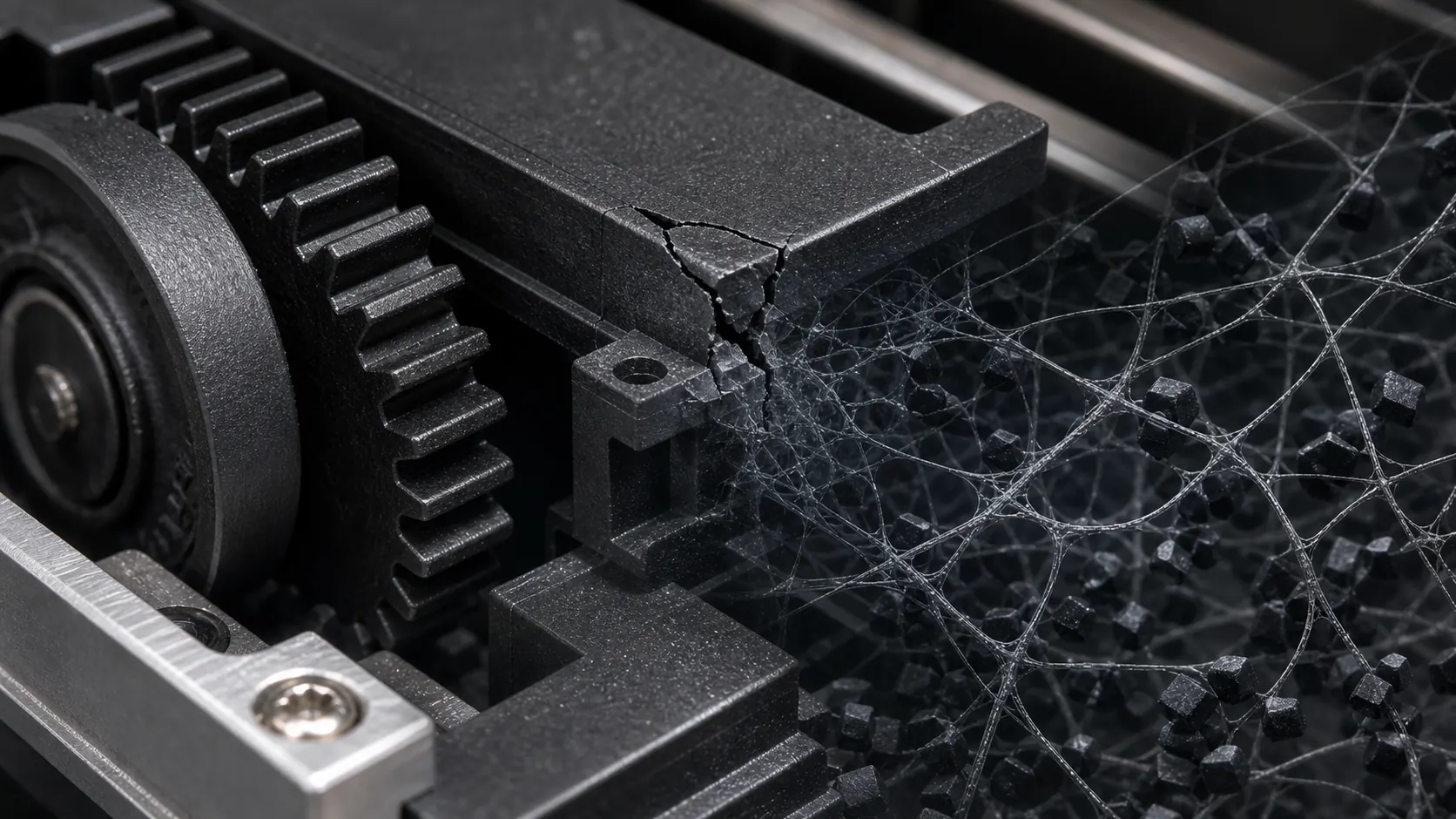
1.2 Poor Dispersion Causes Stress Concentration
Conductive fillers easily agglomerate. Agglomerates behave like hard particles or micro-defects inside the plastic.
Possible failures:
cracking near corners; notch sensitivity; brittle fracture during assembly; unstable resistance between batches; rough surface and poor appearance.
For conductive plastics, dispersion quality often determines whether the material is usable in real parts.
1.3 The Conductive Route Does Not Match the Resin
Different resins require different conductive systems.
PP, ABS, POM, PA, PC/ABS, PE, and PPS do not respond to the same conductive additive in the same way. A conductive masterbatch that works in PP may not be suitable for POM or PA. A high-carbon-black route may reduce toughness too much in parts that need impact or bending.
The route must match:
base resin; target resistance; part thickness; molding method; mechanical target; surface requirement; cost target.
1.4 Conductivity and Toughness Are Not Balanced
Many conductive formulations focus only on resistance. But in real applications, a part often needs both conductivity and toughness.
Examples:
conductive POM gears need conductivity and wear resistance; conductive PP trays need conductivity and impact at corners; conductive ABS covers need conductivity and housing toughness; conductive PA66 components need conductivity and structural strength.
If toughness is ignored, the material may pass electrical testing but fail in assembly or use.
2. Technical Solutions
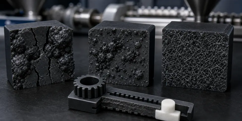
2.1 Use a More Efficient Conductive Network
Instead of increasing filler loading, use a more efficient conductive route.
Possible options:
high-structure conductive carbon black; carbon nanotube conductive network; conductive masterbatch with better dispersion; carbon fiber for conductive + rigidity; hybrid conductive network.
Carbon nanotubes can form a conductive path at lower addition levels in selected systems. This helps reduce the negative effect on toughness and surface quality.
2.2 Improve Dispersion
Dispersion improvement can reduce brittleness caused by filler agglomeration.
Common methods:
better carrier design in conductive masterbatch; higher-quality compounding process; optimized screw combination; proper feeding sequence; controlled shear and residence time; compatibilizer or dispersing aid.
Good dispersion can improve both resistance stability and mechanical reliability.
2.3 Add Toughness Balance
For parts that crack after conductive modification, the formulation may need a toughening system.
Possible methods:
elastomer toughening; resin impact balance; compatibilizer adjustment; surface treatment of conductive filler; fiber interface improvement; hybrid filler balance.
The goal is not to make the material soft, but to improve energy absorption and reduce brittle fracture.
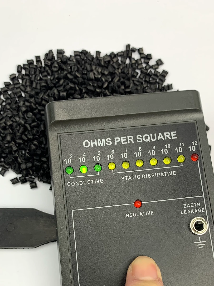
2.4 Avoid Over-Chasing Low Resistance
A common mistake is requiring 10³ Ω when the application only needs 10⁶–10⁸ Ω.
Lower resistance often means:
more conductive filler; higher brittleness risk; worse flowability; rougher surface; higher cost.
A professional selection should first define whether the part needs antistatic, static-dissipative, conductive, or high-conductive performance.
2.5 Validate Final Parts, Not Only Test Bars
Conductive filler orientation is affected by flow direction, wall thickness, gate position, and cooling. A material may perform well on test bars but fail on real parts.
Recommended validation:
surface resistance on final part; notched impact; drop test; snap-fit test; screw boss torque test; wear test if moving part; dimensional stability; surface inspection.
3. DEYU Case Study: DGK-POM DD3-4A Solving Brittleness in Conductive POM Parts
Original Situation
A customer used a conventional carbon black conductive POM for a small mechanical moving part. The part reached the required conductive range, but the material became brittle. During assembly and operation, cracks appeared near thin-wall corners and sliding areas.
Main problems:
conductivity was acceptable; impact strength dropped; surface became rough; part cracked during assembly; wear powder increased during operation; dimensional stability became unstable.
Original Trial Data
| Item | Conventional Conductive POM Trial |
|---|---|
| Surface resistance | 10⁴–10⁶ Ω direction |
| Assembly cracking | 3–5 failures / 20 parts |
| Sliding noise after 100 h | 61 dB |
| Wear depth after 200 h | 0.11 mm |
| Surface quality | Rougher than expected |
| Customer feedback | Conductive but brittle |
DEYU Improvement Plan
DEYU recommended testing DGK-POM DD3-4A, a conductive POM route using a carbon nanotube-based conductive network.
The development idea was not simply to lower resistance, but to reduce brittleness through a more efficient conductive network.
Technical focus:
conductivity around 10⁴–10⁶ Ω direction; lower filler-loading pressure compared with traditional high-carbon-black routes; better surface brightness; improved toughness balance; wear-resistant and sliding performance adjustment; stable molding and part resistance.
Debugging Process
First Trial
The resistance range met the customer’s requirement, and the surface was smoother than the previous carbon black system. However, the sliding part still showed slight noise during long-cycle testing.
Adjustment:
optimized POM base resin balance; improved conductive network dispersion; added wear-resistance adjustment; fine-tuned mold temperature and holding pressure.
Second Trial
Sliding noise decreased, but the customer still wanted better assembly safety at thin-wall corners.
Adjustment:
introduced toughness balance; reduced internal stress through molding parameter optimization; suggested adding small radius at stress concentration areas.
Final Trial
The part passed assembly and sliding validation with lower cracking risk.
Final Result
| Item | Previous Conductive POM | DEYU DGK-POM DD3-4A |
|---|---|---|
| Surface resistance | 10⁴–10⁶ Ω direction | 10⁴–10⁶ Ω direction |
| Assembly cracking | 3–5 / 20 parts | 0–1 / 20 parts |
| Sliding noise after 100 h | 61 dB | 55–56 dB |
| Wear depth after 200 h | 0.11 mm | 0.05–0.06 mm |
| Surface quality | Rougher | Brighter, smoother direction |
| Customer feedback | Conductive but brittle | Conductive with better toughness balance |
Case Conclusion
The solution was not to add more conductive filler. The key was to choose a more suitable conductive route. DGK-POM DD3-4A used a carbon nanotube conductive network to keep the required resistance while improving toughness, surface quality, and sliding performance.
For conductive moving parts, this type of balanced formulation is more reliable than simply chasing the lowest resistance.
4. How to Decide Whether the Material Needs This Route
Choose a balanced conductive route such as DGK-POM DD3-4A when the part has these symptoms:
conductive carbon black makes the material brittle; the part cracks during assembly; resistance is qualified but impact is not; surface quality becomes too rough; wear powder increases; sliding noise becomes worse; the part needs conductivity and wear resistance at the same time; the customer wants conductivity without excessive loss of toughness.
For PP, ABS, PA, PC/ABS, PE, or PPS systems, DEYU can also adjust conductive masterbatch, carbon black, carbon nanotube, carbon fiber, and hybrid conductive routes according to the application.
5. Purchasing Checklist
Before selecting a conductive compound, buyers should confirm:
base resin; target resistance range; whether the part needs antistatic, static-dissipative, or conductive performance; current additive route; current brittle failure mode; impact requirement; elongation requirement; wear requirement; surface appearance; processing method; part thickness; gate position; final part test method; whether flame retardancy, UV resistance, or low warpage is also required.
A clear inquiry should not only say “conductive plastic.” It should describe the current failure: brittle fracture, cracking, rough surface, poor flow, wear powder, unstable resistance, or assembly breakage.
Conclusion
Conductive additives may make modified plastics brittle when the formulation relies on excessive filler loading, poor dispersion, weak interface, or an unsuitable conductive route. The correct solution is not always adding more conductive material. A better method is to build a high-efficiency conductive network, improve dispersion, balance toughness, and validate the final molded part.
The DEYU DGK-POM DD3-4A case shows that a carbon nanotube conductive route can help maintain conductivity while improving toughness, surface quality, and wear behavior. For customers facing “conductive but brittle” problems, the more valuable material is not necessarily the one with the lowest resistance, but the one that keeps conductivity and real-part reliability at the same time.