Two Case Studies for Debugging Conductive and Antistatic Plastic Injection Molding Parameters
A conductive or antistatic compound can pass a data sheet and still fail in the mold. These two cases explain how drying, shear, mold temperature and part-level resistance mapping decide whether the final part keeps its electrical and visual performance.
Article FAQ
Two Case Studies for Debugging Conductive and Antistatic Plastic Injection Molding Parameters
Why can a conductive plastic pass pellet data but fail after injection molding?
The conductive network is rebuilt during melt flow and cooling. Gate shear, filler orientation, weld lines and mold temperature can change the resistance of the final part.
Should PP conductive grades be dried even if PP absorbs little water?
For filled conductive systems, drying is still recommended when the grade sheet specifies it. Moisture can affect filler interfaces, dispersion stability and batch-to-batch resistance.
What is the first check when transparent antistatic ABS becomes hazy?
Check drying, barrel temperature, nozzle temperature and residence time first. Haze often comes from moisture, overheating or non-uniform antistatic-agent dispersion.
How should molded conductive parts be validated?
Measure resistance by zone, especially gate, weld line and flow end. For transparent antistatic ABS, add haze, transmittance and visual defect checks.
Why Conductive Plastics Need Process-Specific Debugging
A commonly underestimated fact is that a conductive plastic grade that performs well on a data sheet does not automatically become a qualified molded part. For functional plastics, injection molding is often the variable that decides final conductivity, mechanical reliability and visual quality.
Conductive fillers and permanent antistatic systems do not behave like inert pigments. Carbon black, carbon fiber, CNT routes or polymeric antistatic agents can orient under shear, redistribute along flow length and freeze into different internal structures. That structure decides where charge can travel.
This guide uses two DEYU cases: DGK-PP DD2-3A conductive PP and DGK-ABS KJD890TM transparent antistatic ABS. The article keeps the original processing logic and enriches it with public site data so mold engineers can connect parameter choices to molded-part validation.
| Molding issue | Typical symptom | Electrical or optical consequence |
|---|---|---|
| Over-shear at a small gate | Low resistance near gate, high resistance at flow end | Filler network becomes directional and non-uniform |
| Fast cooling | Higher resistance, large zone-to-zone variation | Conductive network has insufficient time to reconnect |
| Moisture residue | Silver streaks, bubbles, haze or resistance drift | Interface voids and antistatic system instability |
| Weld line in functional area | Local resistance jumps by one or two orders of magnitude | Conductive path is interrupted at the melt-front meeting line |
| Worn screw or barrel | Batch-to-batch resistance fluctuation | Shear history becomes unstable |
Case 1: DGK-PP DD2-3A Conductive PP
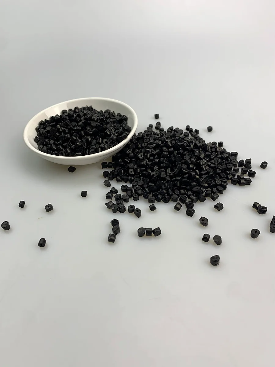
DGK-PP DD2-3A is a low-resistance conductive PP compound. Public DEYU data position it at 10^2-10^3 ohm surface resistance, with tensile modulus of 5570 MPa, flexural modulus of 3472 MPa, Izod notched impact strength of 112 J/m, density of 0.99 g/cm3 and HDT of 107°C. The recommended process window is drying 90°C / 4-5 h, injection temperature 210-220°C and mold temperature 80°C.
The 80°C mold setting is not only for surface finish. For highly conductive PP, it gives the filled melt more time to complete packing and helps the conductive network become less anisotropic before solidification. If the mold is too cold, parts may look complete but show high resistance at flow-end zones.
| Parameter | Site data / starting point | Debugging meaning |
|---|---|---|
| Surface resistance | 10^2-10^3 ohm | Low-resistance target requires continuous filler network |
| Tensile modulus | 5570 MPa | High stiffness indicates high filler influence; gate and screw shear need control |
| Izod notched impact | 112 J/m | Impact is acceptable but should be rechecked after process changes |
| Drying | 90°C, 4-5 h | Controls moisture-sensitive interfaces and batch consistency |
| Injection temperature | 210-220°C | Enough dispersion without PP degradation |
| Mold temperature | 80°C | Supports network recovery and resistance uniformity |
Case 2: DGK-ABS KJD890TM Transparent Antistatic ABS
DGK-ABS KJD890TM is a transparent permanent antistatic ABS. Site data give 10^9-10^10 ohm resistance, light transmittance above 85%, melt flow index 54.6 g/10 min, density 1.115 g/cm3, HDT 84.5°C, Charpy notched impact 12.7 kJ/m2 and Izod notched impact 15.3 kJ/m2. The recommended process window is drying 85°C / 4-5 h, injection temperature 195-210°C and mold temperature 70°C.
For this transparent ABS, process tuning is a double balance. The part must dissipate static, but it must also remain clear. Moisture and overheating can both produce haze; excessive residence time can damage the antistatic system and push resistance upward after conditioning.
| Parameter | Site data / starting point | Debugging meaning |
|---|---|---|
| Resistance | 10^9-10^10 ohm | Dissipative range; verify after conditioning and cleaning |
| Light transmittance | >85% | Haze and streaks are functional defects, not only appearance issues |
| MFI | 54.6 g/10 min | Good flow supports thin transparent covers, but shear heat still matters |
| Drying | 85°C, 4-5 h | Prevents bubbles, silver streaks and hydrolysis-related drift |
| Injection temperature | 195-210°C | Narrower window protects transparency and antistatic agent |
| Mold temperature | 70°C | Improves surface wetting and lowers optical stress |
Shared Process Logic
| Control point | Conductive PP logic | Transparent antistatic ABS logic |
|---|---|---|
| Drying | Even PP should follow 90°C / 4-5 h for this filled system | 85°C / 4-5 h is critical for transparency and resistance stability |
| Gate design | Avoid small gates and long high-shear runners | Avoid jetting, trapped air and optical flow marks |
| Screw speed | Medium-low speed protects conductive filler structure | Moderate speed reduces shear heat and haze |
| Mold temperature | 80°C helps network recovery and flow-end conductivity | 70°C helps clarity, surface gloss and stress reduction |
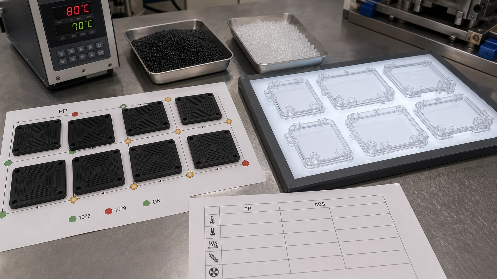
| Validation | Map resistance at gate, weld line and flow end | Measure resistance, haze, transmittance and appearance together |
Field Debugging Matrix
| Problem | Likely cause | First action |
|---|---|---|
| Flow end resistance too high | Cold mold, long flow path or filler orientation | Raise mold temperature, check gate size, map resistance by zone |
| Weld line becomes insulating | Conductive network interrupted where flow fronts meet | Move weld line away from functional contact area or change gate layout |
| Transparent ABS becomes foggy | Moisture, overheating or excessive shear | Confirm drying dew point, reduce barrel/nozzle temperature, lower screw speed |
| Resistance passes but appearance fails | Electrical network is present but optical scattering is high | Treat haze as a functional defect and inspect moisture plus residence time |
| Batch fluctuation after same settings | Screw wear, inconsistent drying or material residence variation | Check screw/barrel wear, drying records and shot-size stability |
Validation Checklist
- Record actual melt temperature, not only barrel setpoints.
- Keep a resistance map for at least gate zone, middle zone, weld line and flow end.
- For transparent ABS, inspect haze and transmittance under consistent light, not only by naked eye.
- Do not batch-switch to new parameters until resistance, impact and appearance pass on molded parts.
- Inspect screw and barrel wear when high-filled conductive grades show unexplained drift.
- Send DEYU the part drawing, gate design, thickness, target resistance, defect photos and process record for faster troubleshooting.
Conclusion
Conductive and antistatic plastics require a molding strategy that respects the material's electrical network, not only a generic resin window. DGK-PP DD2-3A asks the processor to protect a low-resistance filler network, while DGK-ABS KJD890TM asks for a tighter balance between antistatic performance and transparency. The common rule is simple: validate the molded part, not only the pellet.