Flame-Retardant Conductive PP: Balancing UL94 V-0 and Stable Conductivity
Conductive PP and flame-retardant PP are each manageable alone. Combining them is harder because the carbon network that carries charge and the flame-retardant system that builds a protective char layer can disturb each other. This guide explains the conflict, the formulation logic and the validation route for PP compounds that need both UL94 V-0 and stable conductivity.
Article FAQ
Flame-Retardant Conductive PP: Balancing UL94 V-0 and Stable Conductivity
Can a conductive PP compound automatically pass UL94 V-0 if a flame retardant is added?
No. Carbon fillers can disturb the char layer or transfer heat into the polymer. UL94 V-0 must be validated after the conductive system is added and at the real required thickness.
Why can V-0 pass while resistance becomes too high?
High IFR loading can separate the carbon black or CNT network and move the compound below its effective percolation condition. This is why molded-part resistance mapping is required.
When is DGK-PP DD4-5A-JC a relevant reference?
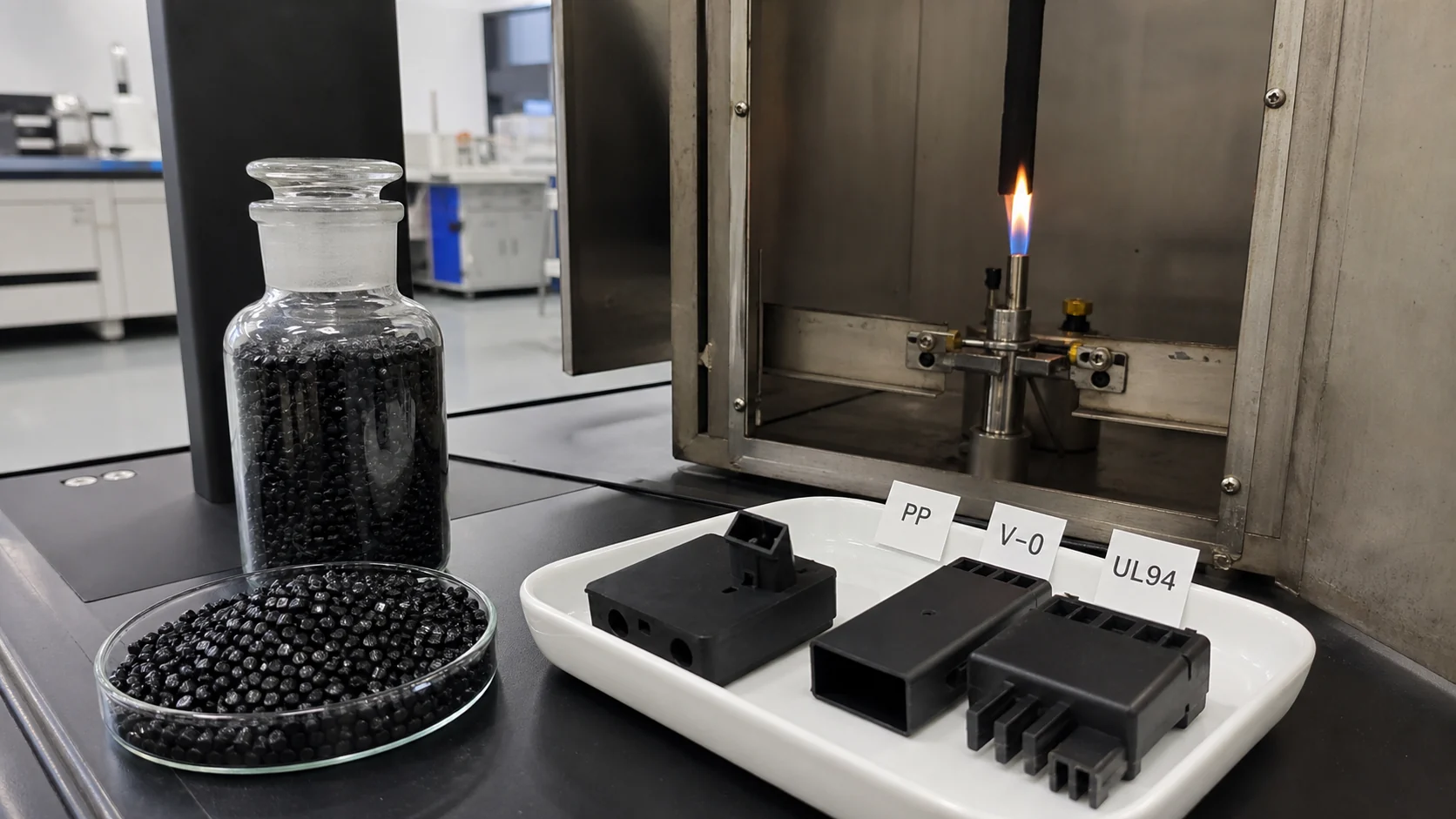
It is relevant when the part needs both conductive PP behavior and UL94 V-0 flame retardancy. Public data show 10^3-10^5 ohm surface resistance and UL-94 V-0.
What information should be sent before custom development?
Send target resistance, UL94 class and thickness, part drawing, wall thickness, gate plan, processing method, mechanical targets, environmental exposure and regulatory requirements.
Why V-0 and Conductivity Pull in Opposite Directions
Polypropylene is widely used for electrical housings, automotive electronics and industrial equipment because it is light, cost-effective, chemically resistant and easy to mold. Its natural limitations are also clear: unmodified PP is a strong electrical insulator, commonly above 10^12 ohm, and it burns rapidly because the hydrocarbon backbone forms little protective char.
For power modules, distribution housings, ESD covers, battery-pack parts and control cabinets, these two weaknesses often have to be corrected at the same time. The target may be UL94 V-0 at a defined thickness plus surface resistance below 10^6 ohm/sq or a stable dissipative range. Adding one flame retardant and one conductive filler is not enough; the two additive systems can interfere during compounding, molding and burning.
For DEYU projects, the most relevant public reference is DGK-PP DD4-5A-JC flame-retardant conductive PP. Where a customer only needs flame retardancy and not conductivity, DGK-PP WPP-V0 halogen-free flame-retardant PP is a separate reference, not a substitute for conductive PP.
| Functional requirement | Typical loading | Possible effect on the other property |
|---|---|---|
| UL94 V-0 flame retardancy | 20-30% IFR or halogen-free FR package | Can physically dilute or separate the conductive filler network |
| Electrical conductivity | 10-20% carbon black or lower CNT loading | Can increase heat transfer, disturb char expansion or create a wick effect |
| Both functions together | Often 30-50% total additives | Can reduce impact strength, flow, weld-line reliability and cost efficiency |
The Technical Antagonism Behind the Failure
Conductive plastics rely on a percolated network of carbon black, carbon fiber, CNT or graphite. The base PP matrix is insulating, so charge can only travel when enough conductive particles touch or approach one another. Any physical separation, poor dispersion or flow-induced orientation can raise resistance by orders of magnitude.
Intumescent flame retardants work differently. During burning, acid source, carbon source and gas source reactions build an expanded char layer at the surface. That layer blocks heat and oxygen. The problem is that carbon fillers can conduct heat, block expansion or change the melt-drip behavior. At high carbon black loading, flame retardancy can even worsen because the filler behaves like a thermal bridge.
The mechanical penalty is the second difficulty. A PP system with 15% conductive carbon black and 30% IFR already reaches 45% total additives. At that level, flow becomes heavy, impact strength falls and thin ribs or snap-fit features become vulnerable. This is why V-0 conductive PP must be formulated as a combined system, not as two independent modifications.
| Failure mode | Typical root cause | Production meaning |
|---|---|---|
| V-0 passes, resistance is too high | IFR particles split the carbon contacts and move the formulation below the effective percolation state | A standard flame bar may pass, but the molded housing does not discharge static reliably |
| Resistance passes, V-0 fails | Carbon black or graphite conducts heat inward and prevents a stable intumescent char barrier | The electrical target is met while the fire-safety target is not |
| Both pass on plaques, part fails | Weld lines, gate shear, wall-thickness change or filler segregation create local weak zones | Part-level mapping is required, not only pellet or plaque data |
| Brittleness and high scrap | Total loading is too high or filler compatibility is poor | Assembly clips, ribs and screw bosses crack even when basic data looks acceptable |
Formulation Routes That Turn Conflict Into Synergy
| Route | How it helps | Main risk to control |
|---|---|---|
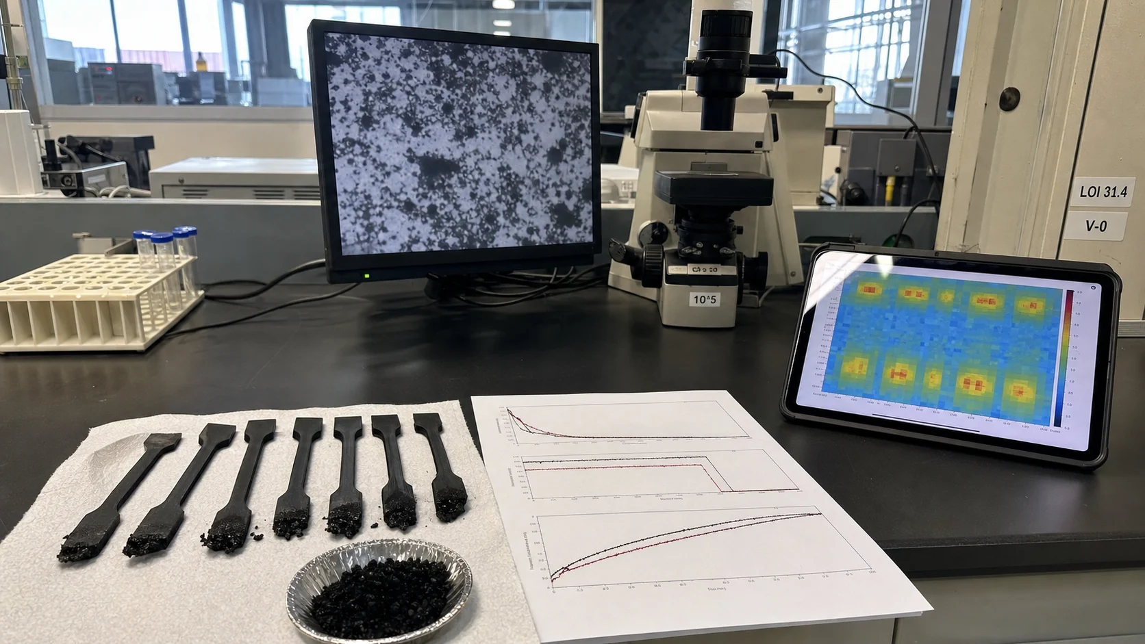
| Optimized carbon black + IFR | Nanosized carbon black can act as both conductor and IFR synergist; literature examples report LOI 31.4% and UL94 V-0 at about 5% CB in PP/IFR routes | Use too much carbon black and the wick/heat-transfer effect can reduce flame retardancy |
| CNT + APP | CNT can form a segregated conductive network and also support char formation; PP/APP/CNT examples show V-0 with 7 wt% CNT and 15 wt% APP | CNT dispersion, cost and conductivity uniformity must be validated on real parts |
| High-efficiency halogen-free FR + carbon synergist | Lower FR loading, for example 20-25%, leaves more room for conductive network and toughness | The system must still pass the required UL94 thickness and aging condition |
| Compatibilized PP system | PP-g-MAH, surface treatment or reactive compatibilizers improve filler-resin contact and reduce agglomeration | Over-compatibilization can change flow, shrinkage or char behavior |
DEYU Material Direction and Public Product Data
| Item | DGK-PP DD4-5A-JC public data | Engineering interpretation |
|---|---|---|
| Material type | Flame-retardant conductive PP, black pellets | Directly relevant to parts needing both V-0 and electrical conductivity |
| Surface resistance | 10^3-10^5 ohm | Conductive range; suitable when ESD or low-resistance dissipation is required |
| Flammability | UL-94 V-0 | Fire-safety validation must still be confirmed at the customer's part thickness |
| Flexural strength / modulus | 22 MPa / 1023 MPa | Additive system lowers stiffness versus reinforced grades; part design should support ribs and bosses |
| Tensile strength / elongation | 21.8 MPa / 90% | Useful elongation helps prevent brittle assembly failure |
| Izod notched impact | 35 kJ/m2 | Impact is strong for a conductive FR PP compound |
| MFI / density / HDT | 7 g/10 min / 0.965 g/cm3 / 105°C | Molding pressure, wall thickness and heat exposure should be checked early |
| Process window | Drying 90°C for 4-5 h; injection 210-225°C; mold 80°C | Start here, then tune by resistance map and UL94 part validation |
Customer Debugging and Validation Scenario
A manufacturer of power-supply housings needed surface resistance below 10^6 ohm/sq, UL94 V-0 and enough impact strength for screw bosses and assembly clips. Its first trial used 15% carbon black and 30% IFR. The flame bar reached V-0, but molded parts measured above 10^10 ohm/sq in several zones, and assembly cracking increased because the total loading reached 45%.
DEYU reviewed the issue as a system failure: the IFR package physically interrupted the carbon black network, while the high total loading reduced flow and toughness. Three alternative routes were proposed for validation: optimized CB/IFR with a synergist, CNT + APP, and a high-efficiency FR package with carbon synergist.
| Property | Original: CB 15% + IFR 30% | Material A: CB 5% + IFR 25% + synergist | Material B: CNT 7% + APP 15% | Material C: efficient FR 20% + CB 5% | Target |
|---|---|---|---|---|---|
| Surface resistance | >10^10 ohm/sq | 5x10^6 ohm/sq | 10^4-10^5 ohm/sq | 8x10^6 ohm/sq | <10^6 ohm/sq |
| UL94 rating | V-0 | V-0 | V-0 | V-0 | V-0 |
| LOI | 30% | 31.4% | Not measured | 28-30% | >28% |
| Impact strength | 2.5 kJ/m2 | 4.5 kJ/m2 | 5.5 kJ/m2 | 4.0 kJ/m2 | >3.5 kJ/m2 |
| Total additive loading | 45% | 30% | 22% | 25% | <35% |
| Molding scrap rate | 12% | 5% | 3% | 4.5% | <5% |
Framework for Result Interpretation
| Step | What to decide | Why it matters |
|---|---|---|
| 1 | Confirm target resistance and test standard | 10^3-10^5 ohm and 10^8-10^10 ohm are different formulation targets |
| 2 | Define UL94 class and thickness | V-0 at 3.0 mm does not prove V-0 at 1.5 mm |
| 3 | Choose carbon filler as a synergist, not only a conductor | CB or CNT can improve char quality when loading and dispersion are controlled |
| 4 | Keep total loading below the mechanical danger zone | Below roughly 35% is often easier for impact, flow and cost |
| 5 | Validate molded parts | Measure resistance at gate, middle, weld line, flow end and thin-wall zones |
Suitable Applications and Buyer Inputs
| Application | Recommended route | Critical requirement |
|---|---|---|
| Electrical distribution housings | CB + IFR synergist route | V-0, low resistance, assembly toughness |
| Power-supply cases | CNT + APP or DD4-5A-JC-type conductive FR PP | V-0, <10^6 ohm/sq, thin-wall stability |
| Automotive electronic covers | CB + halogen-free FR package | Conductivity, heat resistance, vibration durability |
| Industrial control panels | CNT + APP for lower total loading | Surface quality and resistance uniformity |
| Battery-pack components | Conductive FR PP with chemical resistance review | V-0, conductivity and electrolyte-area compatibility |
| Lighting and appliance housings | High-efficiency FR + carbon synergist | Thermal stability, V-0 and molding yield |
- Target surface or volume resistance and the test method.
- UL94 class, required specimen thickness and whether glow-wire data is also needed.
- Part drawing, wall thickness, gate position and weld-line location.
- Processing method: injection molding, extrusion or compression molding.
- Mechanical limits: impact, tensile strength, clip deflection and screw-boss loading.
- Environmental limits: heat, humidity, chemical exposure, RoHS / REACH / halogen-free preference.
- Monthly or annual volume and the target material cost per kg or per part.
Conclusion
V-0 conductive PP is difficult because flame retardants and conductive fillers are not independent. The practical solution is to lower total loading with synergistic carbon routes, validate UL94 at the real thickness, and map resistance on the molded part. DGK-PP DD4-5A-JC provides a public DEYU reference for a flame-retardant conductive PP direction, while custom versions should still be tuned around the customer's resistance target, geometry and compliance requirements.