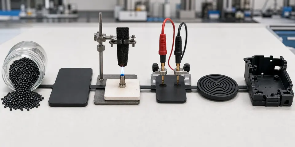
Why Is Flame-Retardant Conductive PP (Polypropylene) Difficult to Stabilize?
This page is for buyers and engineers who need a conductive plastic solution based on real molded-part validation, not only a single resistance reading.
Buyer and engineer FAQ
Questions engineers often ask about this material route
Where can PP with a flame-retardant plastic requirement be used?
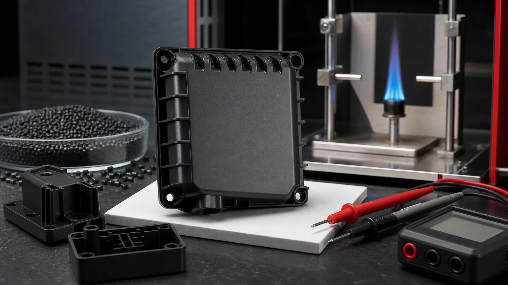
Typical fields include electrical enclosures, battery parts, connectors, appliance housings and industrial covers. For this article, DEYU would first confirm the working environment, wall thickness, expected lifetime and whether DGK-PP DD4-5A-JC Flame Retardant Conductive PP, Flame Retardant Plastics matches the part geometry or needs formulation adjustment.
What are the main performance indicators for the "flame-retardant plastic" target on PP?
Focus on UL94 rating, GWFI/GWIT when needed, CTI, mechanical retention, color stability and flame-retardant precipitation. Buyers should ask for data on molded parts, not only pellet data, because gate position, filler orientation and thickness can change the final value.
What should engineers watch during injection molding or processing?
For PP, a practical starting window is 190-230°C melt / 30-60°C mold. Avoid excessive residence time, use moderate screw speed and confirm the rating at the actual wall thickness. Final parameters should follow part thickness, gate design and the actual machine.
What details help DEYU recommend DGK-PP DD4-5A-JC Flame Retardant Conductive PP, Flame Retardant Plastics more accurately?
Send the current resin or grade, drawing or photo, wall thickness, annual quantity, target standard, failure mode and required color. If a reference grade already passed one test but failed in production, include both data sets.
For a precise recommendation, share the part drawing, base resin, target performance, processing method and test standard with DEYU.
This page is for buyers and engineers who need a conductive plastic solution based on real molded-part validation, not only a single resistance reading.
DGK-PP DD4-5A-JC Flame Retardant Conductive PP and Flame Retardant Plastics. This page focuses on the interaction between flame-retardant additives, conductive fillers and PP molding behavior.
1. Background / Problem
Some electrical, industrial and equipment components require both flame retardancy and ESD or conductive behavior. Standard conductive PP may not meet the flame-retardant requirement, while standard flame-retardant PP may remain insulating.
This creates a formulation conflict. The conductive filler, flame-retardant system, PP base resin and molding stability must all work in the same compound.
2. Technical Difficulty / Why It Happens
Flame-retardant additives can interfere with conductive filler dispersion. Conductive fillers can reduce toughness and affect flame-retardant efficiency. High filler loading can narrow the molding window, especially in thin walls or long-flow parts.
The V-0 direction must be confirmed at the real test thickness and with the correct test method. Resistance must also be checked on molded parts, not only on a standard plaque.
3. DEYU Material Direction
DEYU may recommend DGK-PP DD4-5A-JC as the flame-retardant conductive PP direction. Existing product data positions this grade as black PP with V-0 flame-retardant direction and 10^3-10^5 ohm conductivity, supporting extrusion and injection molding.
4. Reference Product Data
| Property | DGK-PP DD4-5A-JC Direction |
|---|---|
| Base resin | PP |
| Flame-retardant direction | V-0 direction; confirm by test thickness and method |
| Conductive direction | 10^3-10^5 ohm |
| Color | Black |
| Processing | Extrusion / injection molding |
| Typical applications | Flame-retardant conductive sheets, electrical covers and structural parts |
5. Real Customer Application Case
A customer used a PP housing near electrical equipment. The previous flame-retardant PP met the flame direction but was insulating. A conductive PP trial met resistance but did not match the flame-retardant direction and showed short-shot risk.
6. Validation Data Table
| Item | Flame-retardant PP | Conductive PP trial | DEYU DGK-PP DD4-5A-JC trial direction |
|---|---|---|---|
| Trial quantity | 600 pcs | 600 pcs | 1,000 pcs |
| Flame-retardant direction | Meets project direction | Not stable / not target | V-0 direction to be confirmed by test |
| Resistance direction | Insulating | 10^3-10^5 ohm | Target 10^3-10^5 ohm |
| Molding scrap rate | 3.5% | 6.5% | Target <4.5% |
| Short-shot issue | 0.8% | 3.2% | Target <1.5% after flow tuning |
| Assembly cracking | 1.5% | 4.8% | Target <2.5% |
| Resistance out-of-limit rate | Not applicable | 9.5% | Target <5.0% |
| Internal pass rate | 76% | 72% | Target >88% after combined validation |
This case is based on a real customer scenario from DEYU's internal project records.
7. Result Interpretation
The challenge is not choosing between flame retardancy and conductivity. Both functions must work in the same molded PP part while the part still fills, assembles and survives handling.
Buyers should validate flame result, resistance stability and molding or assembly behavior together. A formula that passes one test can still fail the project if the other two groups are ignored.
8. Suitable Applications
- Flame-retardant conductive PP housings
- Electrical covers
- ESD industrial equipment parts
- Black conductive PP components
- Control box parts
- Molded components requiring both flame-retardant direction and resistance control
9. What Buyers Should Provide
Buyers should provide the required flame-retardant level and test thickness, target resistance range, surface or volume resistance requirement, drawing, wall thickness, color requirement, current failure mode, molding equipment and trial volume.
Conclusion
Final selection should be confirmed on the actual molded part: resistance, processing, mechanical behavior, appearance and service conditions need to be evaluated together.