Validierung leitfähiger Kunststoffe: Granulat-, Platten- und Realteildaten
Die Freigabe leitfähiger Kunststoffe darf nicht bei Lieferantendaten oder flachen Platten enden. Realteile zeigen Anschnitt-Ende-Streuung, Bindenähte, Reinigungseffekte und Prozessrisiko.
FAQ für Einkauf und Qualitätsingenieure
Fragen vor Freigabe leitfähiger Kunststoffdaten
Warum reichen Granulat- und Plattendaten nicht aus?
Sie entstehen unter kontrollierten oder vereinfachten Bedingungen und erfassen nicht Anschnitt, Bindenähte, Füllstofforientierung, Skin-Core, Reinigung oder Montagespannung.
Welcher Datenlevel ist entscheidend?
Realteildaten. Granulat dient Screening, Platten liefern eine Basis, Realteile bestätigen die konkrete Anwendung.
Welches DEYU-Produkt wird verlinkt?
Der Fall betrifft leitfähige PA66-Test-Sockets. Eine exakt gleiche Produktseite gibt es nicht, daher wird DGK-PA66 CF15L-CF40L als ähnliche PA66-Referenz gewählt.
Wie viele Teile sollten geprüft werden?
Ein praktisches Protokoll formt 20-50 Teile, konditioniert sie, misst 5-10 Punkte pro Teil und ergänzt Reinigung, Temperaturzyklen, Verschleiß und Maßprüfung.
Dreistufige Validierungshierarchie
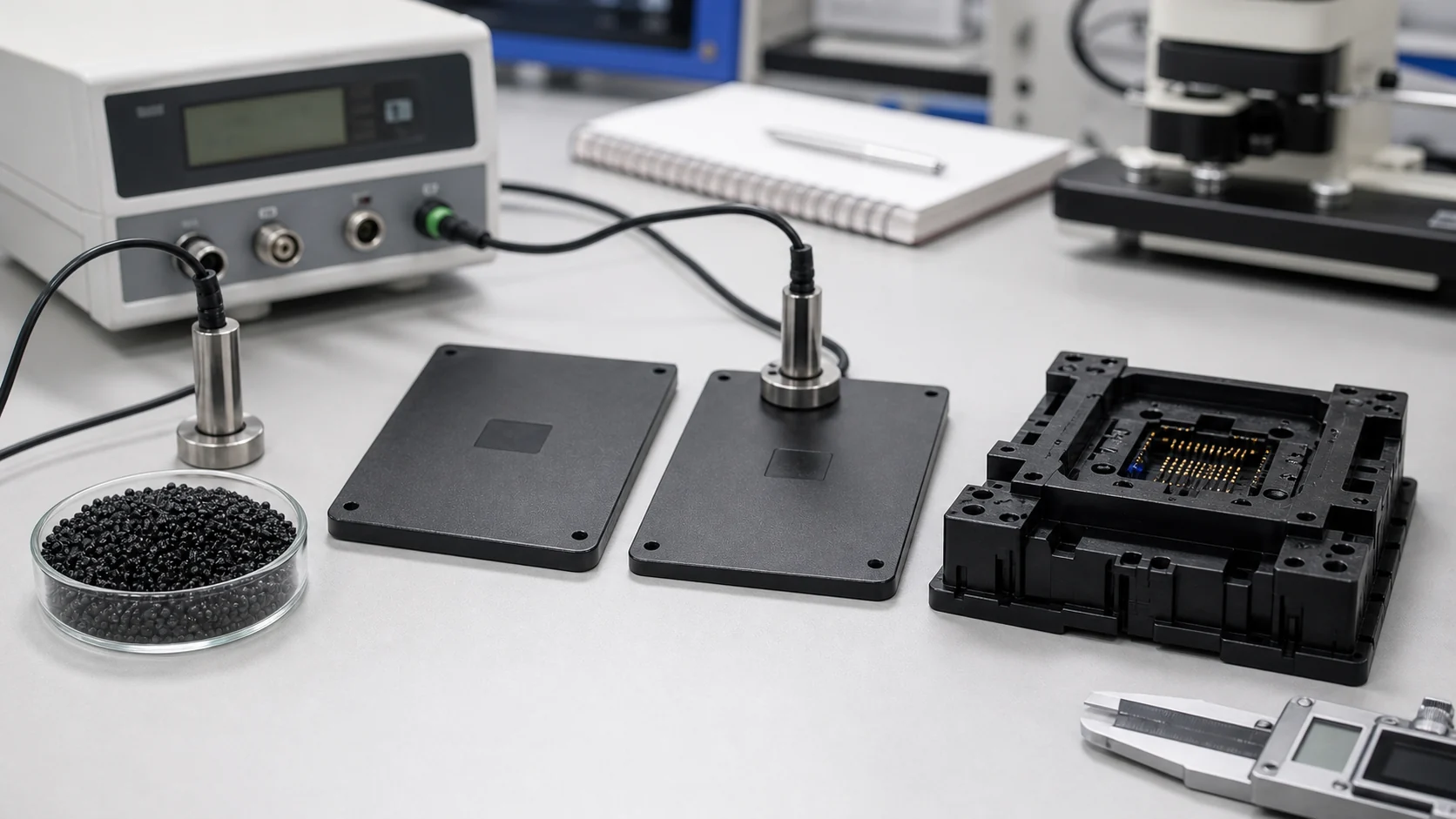
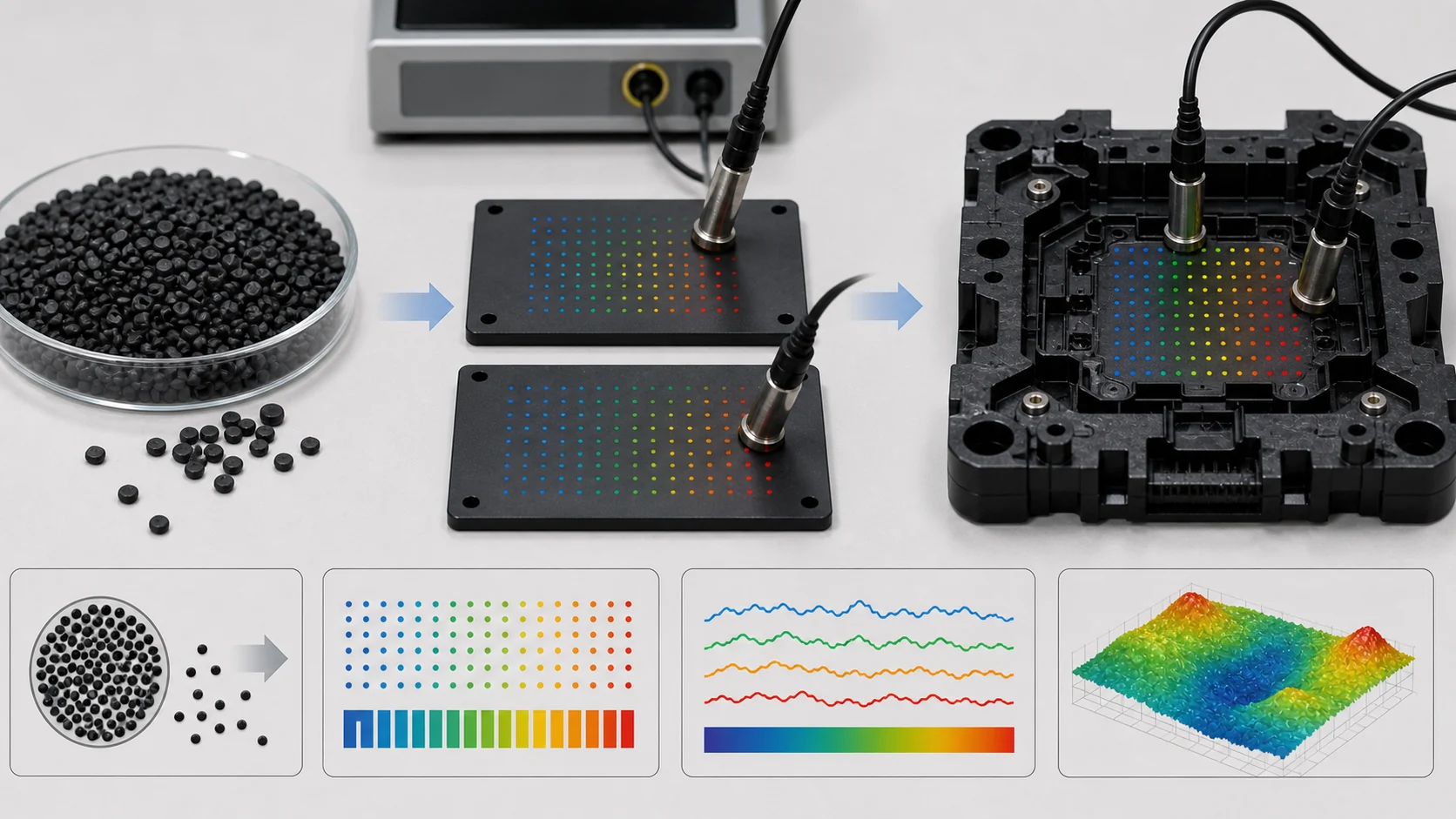
Bei der Qualifizierung leitfähiger Kunststoffe für ESD-Teile gibt es drei Nachweise: Lieferanten-Granulatdaten, Platten-/Coupon-Daten und Realteildaten. Jeder Level hat Nutzen, aber keiner reicht allein.
Level 1: Granulatdaten
Granulatdaten stammen aus Datenblatt und COA. Sie dienen Screening, Einkaufsspezifikation, Referenzbereich und Wareneingang, zeigen aber nicht Anschnitt-Ende-Streuung, Bindenähte, Reinigung oder Montagespannung.
Level 2: Plattendaten
Plattentests nutzen geformte Coupons derselben Charge. Sie prüfen Lieferantendaten und setzen eine Prozessbasis. Eine flache Platte bildet jedoch Rippen, Dome, komplexe Skin-Core-Struktur und Anschnitteffekte nicht ab.
Level 3: Realteildaten
Realteilprüfung erfasst Geometrie, Fluss, Prozess, Skin-Core, Restspannung, Reinigung und Montagebelastung. Im Semiconductor-Socket-Fall ist DGK-PA66 CF15L-CF40L carbon fiber reinforced PA66 pellets die nächste bestehende DEYU-Referenz; keine neue Produktseite wird erstellt.
Referenztabellen zur Validierung
Die Tabellen behalten die englischen Quelldaten zu Hierarchie, Kriterien und Kundenfall bei. Kategoriezeilen sind gefüllt, damit keine leeren Zellen entstehen.
| Level | Data Type | Source | What It Tells You |
|---|---|---|---|
| Level 1 | Pellet data | Supplier datasheet | Intrinsic material properties under ideal conditions |
| Level 2 | Plaque data | In-house testing on molded coupons | Material properties in a standardized geometry |
| Level 3 | Real part data | Testing on actual molded parts | Material performance in the actual application geometry |
| Property | Test Method | What It Shows |
|---|---|---|
| Surface resistivity | ANSI/ESD STM11.11 | Intrinsic surface conductivity of the material |
| Volume resistivity | ASTM D257 | Intrinsic bulk conductivity |
| MFR (melt flow rate) | ASTM D1238 | Processability, flow characteristics |
| Tensile strength | ASTM D638 | Basic strength under tension |
| Flexural modulus | ASTM D790 | Stiffness of the material |
| Notched impact strength | ISO 180/ASTM D256 | Toughness, brittleness |
| HDT (heat deflection temperature) | ISO 75 | Thermal stability |
| UL94 flammability | UL94 | Fire safety rating |
| Density | ASTM D792 | Weight per unit volume |
| Limitation | Why It Matters | Example |
|---|---|---|
| Idealized conditions | Lab conditions differ from production | Pellet data shows resistivity at 23°C/50% RH; production may be 35°C/30% RH |
| Standardized geometry | Coupons are not parts | Flow conditions, gate effects, weld lines, and skin-core structure are absent |
| Single-point measurements | No consideration of variation | Pellet data shows one value; actual parts vary across the part and across batches |
| No processing effects | Molding conditions affect properties | Injection speed, temperature, and pressure change filler orientation and resistivity |
| Purpose | Why It Matters |
|---|---|
| Verification of supplier data | Confirms that the material batch meets specification |
| Incoming quality control | Checks consistency of incoming shipments |
| Comparative evaluation | Compares different material candidates under the same conditions |
| Process development | Establishes baseline processing parameters |
| Gap | Plaque Data | Real Part Reality |
|---|---|---|
| Geometry | Flat, uniform thickness | Variable wall thickness, ribs, bosses, weld lines |
| Flow conditions | Simple, balanced flow | Complex flow with gates, weld lines, flow front variations |
| Filler orientation | Less oriented (some orientation) | Highly oriented in flow direction; varying across part |
| Skin-core structure | Present, but simpler | Complex skin-core structure with variable thickness |
| Gate effects | Minimal (often edge-gated) | Significant near-gate effects on resistivity |
| Stress distribution | Minimal residual stress | Significant residual stress from cooling and packing |
| Environmental exposure | Lab conditions | Cleaning, thermal cycling, chemical exposure, UV |
| Factor | Why It Matters |
|---|---|
| Complex geometry | Flow patterns, filler orientation, and resistivity vary with geometry |
| Gate-to-end variation | Resistivity can vary by 1–3 orders from gate to end-of-fill |
| Weld lines | Resistivity is significantly higher at weld lines |
| Skin-core effects | Surface resistivity may differ from bulk resistivity |
| Processing sensitivity | The material's response to your specific processing conditions |
| Application-specific performance | The only way to validate ESD performance in your application |
| Test | What It Validates | Method |
|---|---|---|
| Multi-point surface resistivity | Uniformity across the part | ANSI/ESD STM11.11 at 5–10 locations per part |
| Critical surface resistivity | Performance on functional surfaces | ANSI/ESD STM11.11 on contact surfaces |
| Resistance to ground (if applicable) | Grounding performance | ANSI/ESD S4.1 (for work surfaces) |
| Post-cleaning resistivity | Cleaning resistance | 50–100 IPA wipe cycles |
| Post-thermal cycling resistivity | Thermal stability | -40°C to +85°C, 100+ cycles |
| Post-wear resistivity | Abrasion resistance | 10,000+ wear cycles |
| Dimensional stability | Part geometry after processing | Precision measurement |
| Assembly performance | Snap-fit, press-fit, or other assembly | Assembly fixture testing |
| Step | Action | Sample Size | Acceptance Criteria |
|---|---|---|---|
| 1 | Mold parts under production-equivalent conditions | 20–50 parts | Consistent process parameters |
| 2 | Condition parts at 23°C / 50% RH for 48+ hours | All parts | Environmental control |
| 3 | Measure surface resistivity at 5–10 locations per part | All parts | All locations within specification |
| 4 | Measure resistance to ground (if applicable) | 3 parts | < 1×10⁹ Ω |
| 5 | Perform cleaning resistance test | 5 parts | Resistivity remains in specification |
| 6 | Perform thermal cycling test | 5 parts | Resistivity remains in specification |
| 7 | Perform wear resistance test | 5 parts | Resistivity remains in specification |
| 8 | Measure dimensional stability | 10 parts | Within drawing tolerances |
| 9 | Analyze data (mean, range, pass/fail) | All parts | ≥ 95% pass rate |
| Aspect | Pellet Data | Plaque Data | Real Part Data |
|---|---|---|---|
| Reliability | Low (idealized) | Medium (standardized) | High (application-specific) |
| Cost | Low (no testing) | Medium (molding plaques) | High (molding parts, testing) |
| Time | Immediate | Days | Weeks |
| Predictive value | Low | Medium | High |
| ESD performance validation | None | Partial | Complete |
| Measurement | Pellet Data (Supplier) | Plaque Data (In-house) | Real Part Data |
|---|---|---|---|
| Surface resistivity (gate area) | 10⁷ Ω | 10⁷ Ω | 10⁷ Ω |
| Surface resistivity (center) | 10⁷ Ω | 10⁷ Ω | 5×10⁷ Ω |
| Surface resistivity (end-of-fill) | 10⁷ Ω | 10⁷ Ω | 3×10⁸ Ω |
| Surface resistivity (weld line) | Not measured | Not measured | 5×10⁸ Ω |
| Surface resistivity (after cleaning) | Not measured | Not measured | 8×10⁸ Ω |
| Part-to-part variation | Not measured | ±0.3 orders | ±0.8 orders |
| Phase | Activity | Data Level | Purpose |
|---|---|---|---|
| Phase 1 | Review supplier datasheet | Pellet data | Initial screening, specification setting |
| Phase 2 | Mold and test plaques | Plaque data | Verify supplier data, establish baseline |
| Phase 3 | Mold real parts under production conditions | Real part data | Validate performance on actual geometry |
| Phase 4 | Test real parts after environmental exposure | Real part data | Validate durability and long-term performance |
| Phase 5 | Analyze data and make final decision | All data | Material approval or rejection |
| Level | Acceptance Criteria | Action |
|---|---|---|
| Pellet data | Within supplier specification | Proceed to plaque testing |
| Plaque data | Within ±0.5 orders of pellet data | Proceed to real part testing |
| Real part data | All locations within specification; < 5% part failure | Approve material |
| Environmental data | Remains within specification | Approve for production |
| Data Level | Documentation Required |
|---|---|
| Pellet data | Supplier datasheet, COA (Certificate of Analysis) |
| Plaque data | Test results with environmental conditions (temperature, humidity) |
| Real part data | Test results with part identification, locations, environmental conditions |
| Environmental data | Test results before and after exposure |
| Aspect | Plaque Data | Real Part Data | Difference |
|---|---|---|---|
| Surface resistivity (gate area) | 10⁵ Ω | 10⁵ Ω | 1× |
| Surface resistivity (center) | 10⁵ Ω | 10⁶ Ω | 10× |
| Surface resistivity (end-of-fill) | 10⁵ Ω | 10⁸ Ω | 1000× |
| Surface resistivity (weld line) | Not measured | 10⁹ Ω | Not measured |
| Part-to-part variation | ±0.2 orders | ±1.2 orders | 6× |
| Parameter | Plaque Data | Real Part Data (After Correction) | Specification |
|---|---|---|---|
| Surface resistivity—gate area | 10⁵ Ω | 10⁵ Ω | <10⁶ Ω |
| Surface resistivity—center | 10⁵ Ω | 10⁶ Ω | <10⁶ Ω |
| Surface resistivity—end-of-fill | 10⁵ Ω | 10⁷ Ω | <10⁶ Ω |
| Surface resistivity—weld line | Not measured | 10⁸ Ω | <10⁶ Ω |
| Part-to-part variation | ±0.2 orders | ±0.4 orders | <0.5 orders |
| ESD failure rate | 0% | 0.5% | <1% |
| Level | Data Type | Purpose | Sufficiency |
|---|---|---|---|
| Level 1 | Pellet data | Initial screening, specification setting | Insufficient alone |
| Level 2 | Plaque data | Verification of supplier data, baseline comparison | Insufficient for complex parts |
| Level 3 | Real part data | Performance validation on actual geometry | Essential for qualification |
Kundenvalidierungsfall
Ein Hersteller von Semiconductor Test Sockets gab leitfähiges PA66 nach Datenblatt und Platte frei. Nach drei Monaten zeigten 5-8% ESD-Ausfälle und Widerstand variierte von 10^5 bis 10^9 Ohm. Mit drei Leveln sank der Fehleranteil auf 0.5%.
Welche Angaben Käufer liefern sollten
Benötigt werden Zeichnung oder 3D, Anschnitt und Bindenähte, Spezifikation und Norm, Pellet-Anforderungen, Plattengeometrie, Realteil-Messpunkte, Umwelttests, Musterzahl, Parameter, Einsatz, Montage, Kriterien, Menge, aktuelles Material und Fehler.
Fazit
Granulat- und Plattendaten sind notwendig, aber unzureichend. Die Freigabe muss mit Realteildaten an der tatsächlichen Formteilgeometrie und realistischer Belastung enden.