Validación de plástico conductor: datos de pellet, placa y pieza real
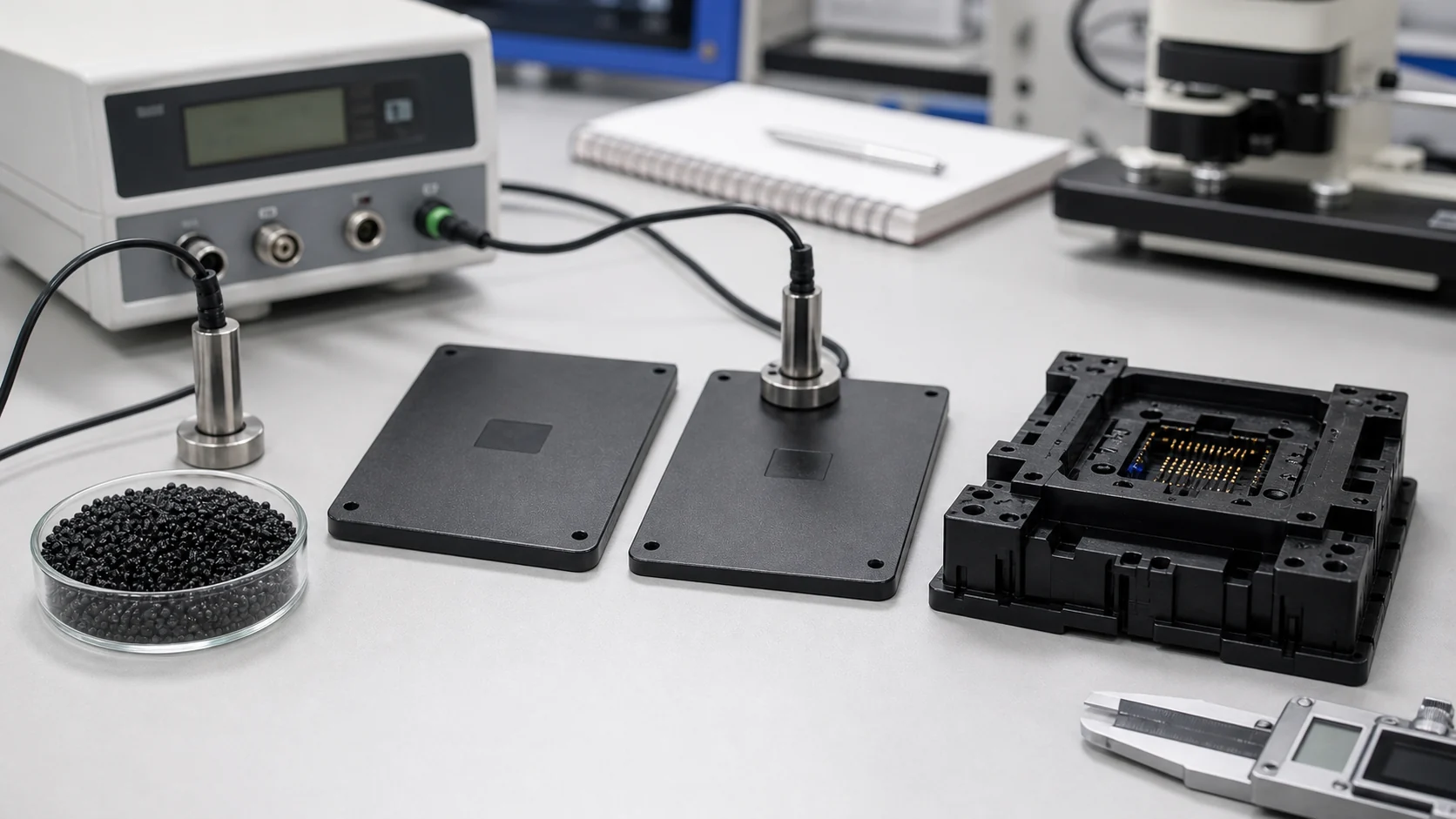
La aprobación de un plástico conductor no debe quedarse en datos de proveedor o placas planas. La pieza real muestra variación de compuerta a final de llenado, líneas de soldadura, limpieza y riesgo de proceso.
FAQ para compradores e ingenieros de calidad
Preguntas antes de aprobar datos de plástico conductor
¿Por qué no bastan pellet y placa?
Porque se miden en condiciones controladas o simplificadas. No capturan compuerta, líneas de soldadura, orientación de relleno, skin-core, limpieza ni esfuerzos de ensamblaje.
¿Cuál es el nivel de validación más importante?
La pieza real. El pellet filtra candidatos, la placa crea una línea base y la pieza real confirma la aplicación.
¿Qué producto DEYU se enlaza?
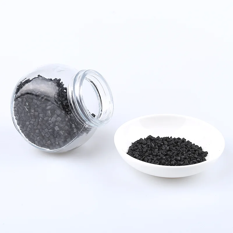
El caso trata sockets de prueba en PA66 conductor. No existe una página exacta, por eso se usa el material similar DGK-PA66 CF15L-CF40L.
¿Cuántas piezas probar?
Un protocolo práctico moldea 20-50 piezas, las acondiciona, mide 5-10 puntos por pieza y añade limpieza, ciclos térmicos, desgaste y control dimensional.
Jerarquía de validación en tres niveles
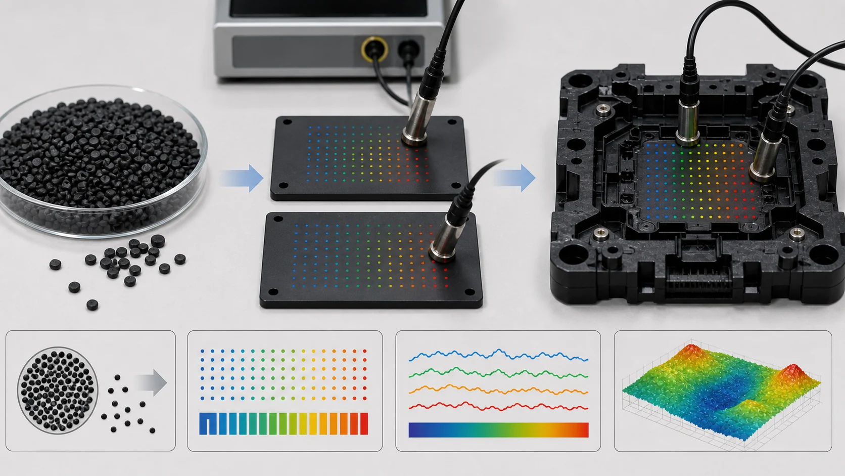
Al calificar un plástico conductor para un componente ESD, ingeniería recibe tres evidencias: datos de pellet del proveedor, datos de placa/coupon moldeado y datos de pieza real. Cada nivel sirve, pero ninguno aprueba por sí solo.
Nivel 1: datos de pellet
Los datos de pellet vienen de hoja técnica y COA. Sirven para screening, especificación de compra, rango de referencia y control de entrada, pero no muestran variación de compuerta a final, soldaduras, limpieza ni esfuerzos de ensamblaje.
Nivel 2: datos de placa
Plaque testing usa coupons moldeados de la misma partida. Verifica datos de proveedor y fija baseline de proceso, pero la placa plana no reproduce nervios, bosses, skin-core complejo ni efectos de compuerta.
Nivel 3: datos de pieza real
La pieza real captura geometría, flujo, proceso, skin-core, tensión residual, limpieza y carga de montaje. En el caso de socket semiconductor, la referencia DEYU más cercana es DGK-PA66 CF15L-CF40L carbon fiber reinforced PA66 pellets; no se crea producto nuevo.
Tablas de validación de referencia
Las tablas conservan los datos fuente en inglés sobre jerarquía, criterios y caso cliente. Las filas de categoría están rellenadas para evitar celdas vacías.
| Level | Data Type | Source | What It Tells You |
|---|---|---|---|
| Level 1 | Pellet data | Supplier datasheet | Intrinsic material properties under ideal conditions |
| Level 2 | Plaque data | In-house testing on molded coupons | Material properties in a standardized geometry |
| Level 3 | Real part data | Testing on actual molded parts | Material performance in the actual application geometry |
| Property | Test Method | What It Shows |
|---|---|---|
| Surface resistivity | ANSI/ESD STM11.11 | Intrinsic surface conductivity of the material |
| Volume resistivity | ASTM D257 | Intrinsic bulk conductivity |
| MFR (melt flow rate) | ASTM D1238 | Processability, flow characteristics |
| Tensile strength | ASTM D638 | Basic strength under tension |
| Flexural modulus | ASTM D790 | Stiffness of the material |
| Notched impact strength | ISO 180/ASTM D256 | Toughness, brittleness |
| HDT (heat deflection temperature) | ISO 75 | Thermal stability |
| UL94 flammability | UL94 | Fire safety rating |
| Density | ASTM D792 | Weight per unit volume |
| Limitation | Why It Matters | Example |
|---|---|---|
| Idealized conditions | Lab conditions differ from production | Pellet data shows resistivity at 23°C/50% RH; production may be 35°C/30% RH |
| Standardized geometry | Coupons are not parts | Flow conditions, gate effects, weld lines, and skin-core structure are absent |
| Single-point measurements | No consideration of variation | Pellet data shows one value; actual parts vary across the part and across batches |
| No processing effects | Molding conditions affect properties | Injection speed, temperature, and pressure change filler orientation and resistivity |
| Purpose | Why It Matters |
|---|---|
| Verification of supplier data | Confirms that the material batch meets specification |
| Incoming quality control | Checks consistency of incoming shipments |
| Comparative evaluation | Compares different material candidates under the same conditions |
| Process development | Establishes baseline processing parameters |
| Gap | Plaque Data | Real Part Reality |
|---|---|---|
| Geometry | Flat, uniform thickness | Variable wall thickness, ribs, bosses, weld lines |
| Flow conditions | Simple, balanced flow | Complex flow with gates, weld lines, flow front variations |
| Filler orientation | Less oriented (some orientation) | Highly oriented in flow direction; varying across part |
| Skin-core structure | Present, but simpler | Complex skin-core structure with variable thickness |
| Gate effects | Minimal (often edge-gated) | Significant near-gate effects on resistivity |
| Stress distribution | Minimal residual stress | Significant residual stress from cooling and packing |
| Environmental exposure | Lab conditions | Cleaning, thermal cycling, chemical exposure, UV |
| Factor | Why It Matters |
|---|---|
| Complex geometry | Flow patterns, filler orientation, and resistivity vary with geometry |
| Gate-to-end variation | Resistivity can vary by 1–3 orders from gate to end-of-fill |
| Weld lines | Resistivity is significantly higher at weld lines |
| Skin-core effects | Surface resistivity may differ from bulk resistivity |
| Processing sensitivity | The material's response to your specific processing conditions |
| Application-specific performance | The only way to validate ESD performance in your application |
| Test | What It Validates | Method |
|---|---|---|
| Multi-point surface resistivity | Uniformity across the part | ANSI/ESD STM11.11 at 5–10 locations per part |
| Critical surface resistivity | Performance on functional surfaces | ANSI/ESD STM11.11 on contact surfaces |
| Resistance to ground (if applicable) | Grounding performance | ANSI/ESD S4.1 (for work surfaces) |
| Post-cleaning resistivity | Cleaning resistance | 50–100 IPA wipe cycles |
| Post-thermal cycling resistivity | Thermal stability | -40°C to +85°C, 100+ cycles |
| Post-wear resistivity | Abrasion resistance | 10,000+ wear cycles |
| Dimensional stability | Part geometry after processing | Precision measurement |
| Assembly performance | Snap-fit, press-fit, or other assembly | Assembly fixture testing |
| Step | Action | Sample Size | Acceptance Criteria |
|---|---|---|---|
| 1 | Mold parts under production-equivalent conditions | 20–50 parts | Consistent process parameters |
| 2 | Condition parts at 23°C / 50% RH for 48+ hours | All parts | Environmental control |
| 3 | Measure surface resistivity at 5–10 locations per part | All parts | All locations within specification |
| 4 | Measure resistance to ground (if applicable) | 3 parts | < 1×10⁹ Ω |
| 5 | Perform cleaning resistance test | 5 parts | Resistivity remains in specification |
| 6 | Perform thermal cycling test | 5 parts | Resistivity remains in specification |
| 7 | Perform wear resistance test | 5 parts | Resistivity remains in specification |
| 8 | Measure dimensional stability | 10 parts | Within drawing tolerances |
| 9 | Analyze data (mean, range, pass/fail) | All parts | ≥ 95% pass rate |
| Aspect | Pellet Data | Plaque Data | Real Part Data |
|---|---|---|---|
| Reliability | Low (idealized) | Medium (standardized) | High (application-specific) |
| Cost | Low (no testing) | Medium (molding plaques) | High (molding parts, testing) |
| Time | Immediate | Days | Weeks |
| Predictive value | Low | Medium | High |
| ESD performance validation | None | Partial | Complete |
| Measurement | Pellet Data (Supplier) | Plaque Data (In-house) | Real Part Data |
|---|---|---|---|
| Surface resistivity (gate area) | 10⁷ Ω | 10⁷ Ω | 10⁷ Ω |
| Surface resistivity (center) | 10⁷ Ω | 10⁷ Ω | 5×10⁷ Ω |
| Surface resistivity (end-of-fill) | 10⁷ Ω | 10⁷ Ω | 3×10⁸ Ω |
| Surface resistivity (weld line) | Not measured | Not measured | 5×10⁸ Ω |
| Surface resistivity (after cleaning) | Not measured | Not measured | 8×10⁸ Ω |
| Part-to-part variation | Not measured | ±0.3 orders | ±0.8 orders |
| Phase | Activity | Data Level | Purpose |
|---|---|---|---|
| Phase 1 | Review supplier datasheet | Pellet data | Initial screening, specification setting |
| Phase 2 | Mold and test plaques | Plaque data | Verify supplier data, establish baseline |
| Phase 3 | Mold real parts under production conditions | Real part data | Validate performance on actual geometry |
| Phase 4 | Test real parts after environmental exposure | Real part data | Validate durability and long-term performance |
| Phase 5 | Analyze data and make final decision | All data | Material approval or rejection |
| Level | Acceptance Criteria | Action |
|---|---|---|
| Pellet data | Within supplier specification | Proceed to plaque testing |
| Plaque data | Within ±0.5 orders of pellet data | Proceed to real part testing |
| Real part data | All locations within specification; < 5% part failure | Approve material |
| Environmental data | Remains within specification | Approve for production |
| Data Level | Documentation Required |
|---|---|
| Pellet data | Supplier datasheet, COA (Certificate of Analysis) |
| Plaque data | Test results with environmental conditions (temperature, humidity) |
| Real part data | Test results with part identification, locations, environmental conditions |
| Environmental data | Test results before and after exposure |
| Aspect | Plaque Data | Real Part Data | Difference |
|---|---|---|---|
| Surface resistivity (gate area) | 10⁵ Ω | 10⁵ Ω | 1× |
| Surface resistivity (center) | 10⁵ Ω | 10⁶ Ω | 10× |
| Surface resistivity (end-of-fill) | 10⁵ Ω | 10⁸ Ω | 1000× |
| Surface resistivity (weld line) | Not measured | 10⁹ Ω | Not measured |
| Part-to-part variation | ±0.2 orders | ±1.2 orders | 6× |
| Parameter | Plaque Data | Real Part Data (After Correction) | Specification |
|---|---|---|---|
| Surface resistivity—gate area | 10⁵ Ω | 10⁵ Ω | <10⁶ Ω |
| Surface resistivity—center | 10⁵ Ω | 10⁶ Ω | <10⁶ Ω |
| Surface resistivity—end-of-fill | 10⁵ Ω | 10⁷ Ω | <10⁶ Ω |
| Surface resistivity—weld line | Not measured | 10⁸ Ω | <10⁶ Ω |
| Part-to-part variation | ±0.2 orders | ±0.4 orders | <0.5 orders |
| ESD failure rate | 0% | 0.5% | <1% |
| Level | Data Type | Purpose | Sufficiency |
|---|---|---|---|
| Level 1 | Pellet data | Initial screening, specification setting | Insufficient alone |
| Level 2 | Plaque data | Verification of supplier data, baseline comparison | Insufficient for complex parts |
| Level 3 | Real part data | Performance validation on actual geometry | Essential for qualification |
Escenario de validación del cliente
Un fabricante de semiconductor test socket aprobó PA66 conductor con datasheet y placa. Tres meses después, 5-8% de sockets fallaban ESD y la resistencia variaba de 10^5 a 10^9 ohm. Con protocolo de tres niveles, el fallo ESD bajó a 0.5%.
Qué debe aportar el comprador
Aporte plano o 3D, compuerta y soldaduras, especificación y norma, requisitos de pellet, geometría de placa, puntos de pieza real, pruebas ambientales, muestra, parámetros, servicio, montaje, criterios, volumen, material actual y fallos.
Conclusión
Los datos de pellet y placa son necesarios, pero insuficientes. La aprobación debe terminar con datos de pieza real medidos en la geometría moldeada y bajo exposición realista.