
Carbon Black Conductive Plastics: Percolation Threshold and Application Selection
Carbon black is the most widely used conductive additive for plastics. It is inexpensive, readily available, and can transform insulating polymers into materials that dissipate static electricity, protect against electrostatic discharge (ESD), and provide moderate electromagnetic interference (EMI) shielding.
Buyer and engineer FAQ
Questions engineers often ask about this material route
Where can PP / PE with a conductive plastic requirement be used?
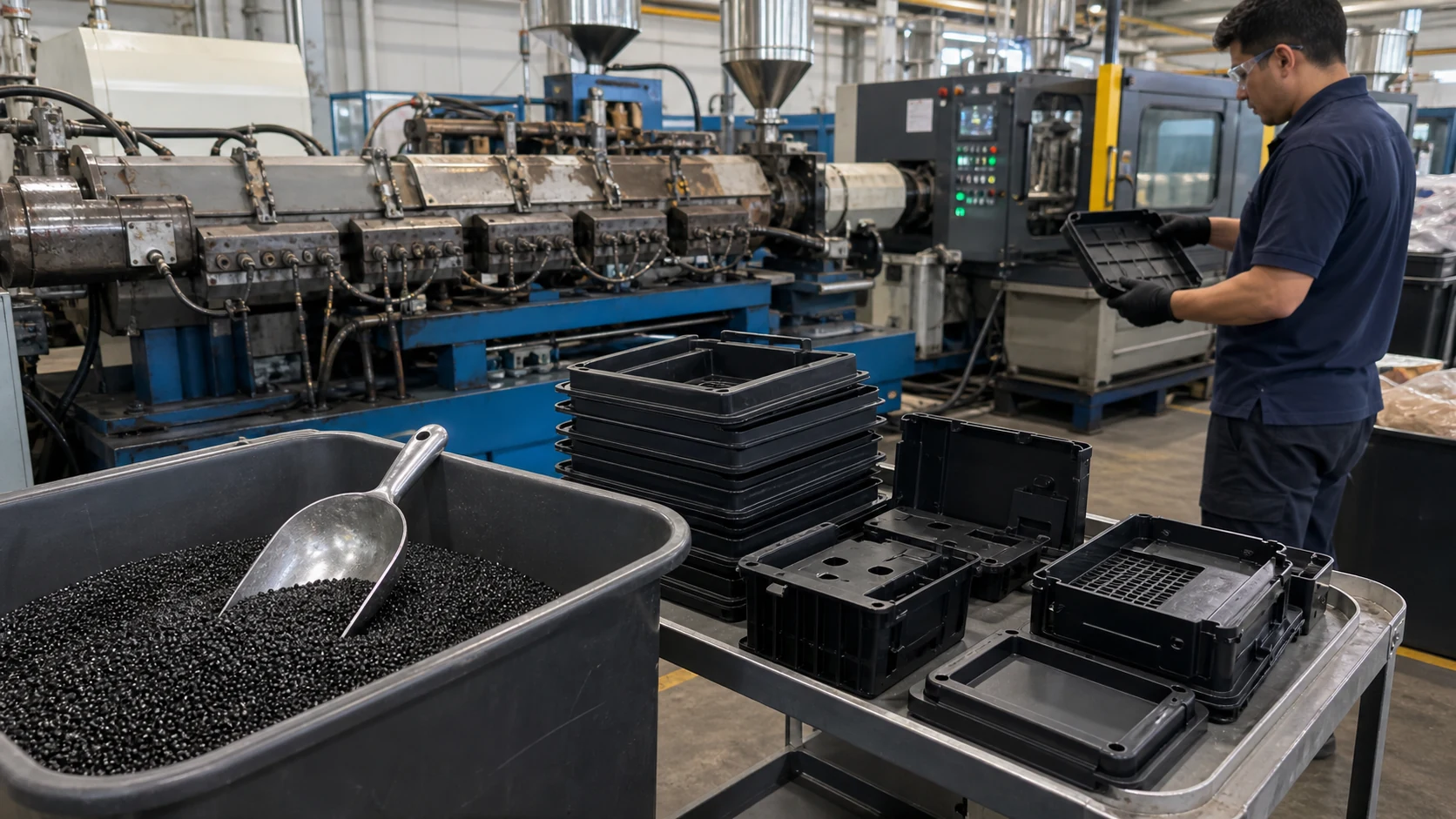
Typical fields include ESD trays, electronic housings, fixtures, EMI parts and antistatic logistics parts. For this article, DEYU would first confirm the working environment, wall thickness, expected lifetime and whether DGK-ABS DD3C graphite conductive ABS, DGK-PP DD4-5A-JC flame-retardant conductive PP matches the part geometry or needs formulation adjustment.
What are the main performance indicators for the "conductive plastic" target on PP / PE?
Focus on surface resistance, volume resistance, dispersion uniformity, impact strength and molding stability. Buyers should ask for data on molded parts, not only pellet data, because gate position, filler orientation and thickness can change the final value.
What should engineers watch during injection molding or processing?
For PP / PE, a practical starting window is 190-230°C melt / 30-60°C mold. Avoid excessive filler loading, control weld lines and verify resistance on the molded part. Final parameters should follow part thickness, gate design and the actual machine.
What details help DEYU recommend DGK-ABS DD3C graphite conductive ABS, DGK-PP DD4-5A-JC flame-retardant conductive PP more accurately?
Send the current resin or grade, drawing or photo, wall thickness, annual quantity, target standard, failure mode and required color. If a reference grade already passed one test but failed in production, include both data sets.
For a precise recommendation, share the part drawing, base resin, target performance, processing method and test standard with DEYU.
Background / Problem
Carbon black is the most widely used conductive additive for plastics. It is inexpensive, readily available, and can transform insulating polymers into materials that dissipate static electricity, protect against electrostatic discharge (ESD), and provide moderate electromagnetic interference (EMI) shielding.
Related DEYU plastics material references for this selection topic: DGK-ABS DD3C graphite conductive ABS and DGK-PP DD4-5A-JC flame-retardant conductive PP.
The core challenge: Carbon black is not a simple additive. Its performance depends on particle size, structure (aggregate morphology), surface area, loading concentration, and dispersion quality. Achieving the right conductivity requires understanding the percolation threshold — the critical concentration at which carbon black particles form a continuous conductive network through the polymer matrix.
The fundamental trade-off: Increasing carbon black loading to achieve lower resistivity reduces mechanical properties — impact strength, elongation at break, and flow. The art of carbon black compounding is finding the optimal loading that meets the conductivity target while preserving acceptable mechanical performance and processability.
This page provides a systematic technical analysis of carbon black conductive plastics — covering the physics of conductivity, the advantages and limitations of the carbon black route, grade selection, and application-specific guidance.
Technical Difficulty / How Carbon Black Creates Conductivity
1. The Percolation Threshold — The Critical Concept
Carbon black is intrinsically a semiconductor. At very low loadings (such as those used for color pigmentation), the compound resistivity remains at the level of the unfilled polymer. As carbon black loading increases, a critical concentration is reached where carbon black aggregates begin to contact each other, forming a continuous conductive pathway through the insulating polymer matrix.
This region of rapid resistivity decrease — typically 8–10 orders of magnitude over a narrow loading range — is called the percolation region. At the percolation threshold, the composite transitions from an insulator to a conductor. Above this threshold, resistivity reaches a plateau that is still 1–2 orders of magnitude higher than that of dry carbon black.
The percolation threshold varies significantly depending on:
| Factor | Effect on Percolation Threshold | Mechanism |
|---|---|---|
| Particle size | Smaller particles → lower threshold | More particles per unit volume; shorter inter-particle distances |
| Structure (aggregate morphology) | Higher structure → lower threshold | Branched aggregates create more conductive pathways |
| Surface area | Higher surface area → lower threshold | More contact points between particles |
| Polymer matrix | Higher crystallinity → higher threshold | Crystallization excludes filler to amorphous regions |
| Interphase thickness | Thicker interphase → lower threshold | Reduces space between nanoparticles |
Research shows that percolation thresholds for carbon black can range from as low as 0.01 wt% for optimal nanoparticle configurations to over 10 wt% for conventional grades in crystalline polymers. For example, PLA/CB composites show an electrical percolation threshold around 5.13 wt%, while HDPE/CB composites show approximately 10.72 wt%.
2. The Conduction Mechanism — Electron Tunneling and Hopping
Below the percolation threshold, carbon black particles are separated by insulating polymer gaps. Conduction occurs through electron tunneling and hopping — electrons jump across the thin insulating barriers between adjacent carbon black aggregates.
At the percolation threshold, the gaps between aggregates become small enough that tunneling becomes efficient, creating a dramatic increase in conductivity. The electron tunneling mechanism is influenced by:
Inter-particle distance — shorter distances reduce tunneling resistance
Interphase conductivity — the polymer region immediately surrounding each particle can act as an electron hopping duct
Particle connectivity — the number and quality of contacts between aggregates
3. Temperature Dependence of Resistivity
Carbon black-filled composites exhibit temperature-dependent resistivity. Below the percolation threshold, the temperature coefficient of resistance can change from negative to positive at specific concentrations. This behavior is important for applications where temperature varies significantly — resistivity may drift with temperature, affecting ESD performance.
4. The Role of Carbon Black Properties
Not all carbon blacks are equal. Key properties that affect conductive performance:
| Property | Effect on Conductivity | Effect on Processing |
|---|---|---|
| Particle size (surface area) | Smaller particles → higher conductivity at lower loadings | Higher surface area → higher viscosity, harder to disperse |
| Structure (aggregate morphology) | Higher structure → higher conductivity | Higher structure → higher viscosity |
| Porosity | Higher porosity → higher conductivity | May affect dispersion |
| Surface chemistry | Affects polymer interaction and dispersion | Affects compounding and stability |
Conductive carbon blacks are specifically engineered with high surface area, high structure, and high porosity to maximize conductivity at minimal loadings.
DEYU Material Direction — Carbon Black Compounding Approach
DEYU approaches carbon black conductive compounding through a systematic methodology:
1. Filler Selection Based on Application Requirements
DEYU evaluates multiple carbon black grades for each application:
| Carbon Black Type | Key Characteristics | Best Suited For |
|---|---|---|
| Standard conductive black | Moderate surface area, balanced properties | General ESD applications |
| High-structure conductive black | High conductivity at lower loadings | Applications requiring property preservation |
| Acetylene black | High purity, good conductivity | Specialized applications |
| High-surface-area black | Very high conductivity | Demanding conductivity requirements |
2. Loading Optimization — Minimum Effective Concentration
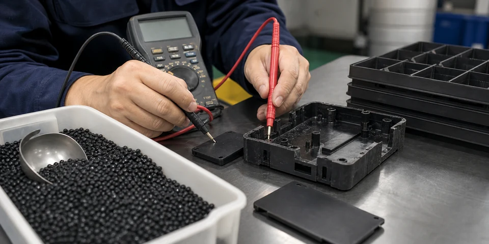
DEYU determines the minimum carbon black loading required to achieve the target resistivity. This approach:
Preserves mechanical properties (impact strength, elongation)
Maintains flow and processability
Minimizes cost
Reduces surface appearance issues
3. Dispersion Quality Control
Poor dispersion creates agglomerates that act as stress concentrators and reduce conductivity. DEYU ensures:
Optimal compounding shear and temperature
Proper mixing time and sequence
Compatibilizers or coupling agents where needed
4. Formulation Balance
DEYU balances carbon black loading with:
Impact modifiers to restore toughness lost at high loadings
Processing aids to maintain flow
Stabilizers for thermal and UV protection
Reference Product Data — Carbon Black Conductive Compounds
The table below provides reference data for carbon black-filled conductive compounds across different base resins. All values are directional.
| Property | DGK-PP-CB (ESD General) | DGK-ABS-CB (High Impact) | DGK-PE-CB (Extrusion) | DGK-PA6-CB (High Toughness) |
|---|---|---|---|---|
| Base Resin | PP | ABS | LDPE/HDPE | PA6 |
| Carbon Black Loading | 12–15% | 12–15% | 15–20% | 10–15% |
| Processing Method | Injection molding | Injection molding | Extrusion, blow molding | Injection molding |
| Surface Resistivity (Ω/sq) | 10⁵ – 10⁹ | 10⁵ – 10⁹ | 10⁵ – 10⁹ | 10⁵ – 10⁸ |
| Volume Resistivity (Ω·cm) | 10⁶ – 10¹⁰ | 10⁶ – 10¹⁰ | 10⁶ – 10¹⁰ | 10⁶ – 10⁹ |
| Density (g/cm³) | 0.95 – 1.02 | 1.10 – 1.18 | 0.98 – 1.05 | 1.10 – 1.18 |
| MFR (g/10min) | 5 – 15 | 5 – 20 | 1 – 10 | 5 – 15 |
| Tensile Strength (MPa) | 22 – 28 | 40 – 50 | 18 – 25 | 45 – 55 |
| Flexural Modulus (MPa) | 1,500 – 2,500 | 3,500 – 5,000 | 800 – 1,500 | 2,500 – 3,500 |
| Notched Impact (kJ/m²) | 3 – 5 | 6 – 10 | 2 – 4 | 6 – 10 |
| HDT @ 1.82 MPa (°C) | 90 – 105 | 85 – 100 | 70 – 85 | 70 – 85 |
| Humidity Dependence | Low (carbon-based) | Low (carbon-based) | Low (carbon-based) | Low (carbon-based) |
| Typical Applications | IC trays, packaging, ESD flooring | Electronic housings, trays | Conductive films, tubing | High-toughness ESD parts |
Customer Debugging / Validation Scenario
Context: A manufacturer of IC handling trays was using a carbon black-filled PP compound with a target surface resistivity of 10⁶–10⁸ Ω/sq. The material passed all incoming quality checks. However, production was experiencing a 9% reject rate — parts showed resistivity values ranging from 10⁶ Ω/sq near the gate to >10¹⁰ Ω/sq at weld lines and end-of-fill locations.
Problem analysis: Three issues were identified:
Inconsistent carbon black dispersion — the compounder was not achieving uniform dispersion, creating localized areas with low carbon black concentration
Inadequate carbon black loading — the loading was at the percolation threshold for the specific carbon black grade used, making resistivity highly sensitive to processing variations
Processing sensitivity — the melt temperature and injection speed were at the upper end of the recommended range, causing some carbon black degradation and reduced conductivity
Trial structure:
| Parameter | Value |
|---|---|
| Trial Quantity | 1,000 trays (5 molding cycles) |
| Monthly Production | 200,000 trays |
| Existing Reject Rate | 9% (resistivity-related) |
| Target Surface Resistivity | 10⁶ – 10⁸ Ω/sq |
DEYU interventions:
Carbon black grade change — switched to a high-structure conductive carbon black with better conductivity at the same loading
Loading optimization — increased loading from 13% to 15% to move well above the percolation threshold, reducing sensitivity to processing variations
Dispersion improvement — optimized compounding parameters (higher shear, longer mixing time) to achieve more uniform dispersion
Process window definition — provided recommended melt temperature and injection speed ranges for stable resistivity
Validation Data Table (customer internal trial structure):
| Parameter | Existing Material + Process | DEYU Material + Optimized Process | Improvement Direction |
|---|---|---|---|
| Resistivity near gate (Ω/sq) | 5×10⁶ | 4×10⁶ | Stable |
| Resistivity at weld line (Ω/sq) | 8×10⁹ | 6×10⁶ | Improved 1,300x |
| Resistivity at end of fill (Ω/sq) | 2×10⁹ | 7×10⁶ | Improved |
| Resistivity variation (max/min) | 1,600:1 | 2:1 | Dramatically improved |
| Molding Scrap Rate | 9% | 2.5% | Reduced |
| Impact Strength (kJ/m²) | 3.2 | 3.8 | Slightly improved |
Result Interpretation:
Existing material analysis: The carbon black loading was at the percolation threshold. Small variations in processing — melt temperature drift, injection speed changes — caused the carbon black network to break and reform, resulting in inconsistent resistivity. The weld line, where carbon black concentration was naturally lower, showed the highest resistivity.
DEYU material + optimized process: The high-structure carbon black and increased loading moved the material well above the percolation threshold, making resistivity much less sensitive to processing variations. The improved dispersion eliminated localized low-conductivity zones. The weld line resistivity dropped from 8×10⁹ Ω/sq to 6×10⁶ Ω/sq — a 1,300x improvement.
DEYU plastics' contribution: DEYU provided three interconnected solutions: (1) a high-structure carbon black grade that provides better conductivity at the same loading, (2) optimized loading to move above the percolation threshold, and (3) a defined processing window to ensure stable resistivity in production.
Next steps: Full production validation across all tray sizes. DEYU can provide ongoing technical support and in-process resistivity monitoring protocols.
Result Interpretation — Carbon Black Selection Framework
Based on the analysis and scenario above, DEYU recommends the following framework for carbon black conductive compound selection:
Step 1 — Define the conductivity target:
| Target Resistivity | Application Type | Recommended Approach |
|---|---|---|
| 10⁹ – 10¹¹ Ω/sq (antistatic) | Dust prevention, packaging | Low carbon black loading, or use of permanent anti-static technology |
| 10⁵ – 10⁹ Ω/sq (dissipative) | IC trays, ESD packaging, housings | Moderate carbon black loading (12–15%) |
| 10⁴ – 10⁵ Ω/sq (semi-conductive) | Conductive components | Higher carbon black loading (15–20%) |
| <10⁴ Ω/sq (conductive) | EMI shielding, grounding | Very high loading or alternative fillers (carbon fiber, CNT) |
Step 2 — Select the carbon black grade:
| Requirement | Recommended Carbon Black Type |
|---|---|
| Cost-sensitive, moderate conductivity | Standard conductive black |
| Property preservation, lower loading | High-structure conductive black |
| High conductivity with minimal loading | High-surface-area conductive black |
| High purity, specialized applications | Acetylene black |
Step 3 — Optimize loading:
Start at the minimum loading that achieves target resistivity
Test at the extremes of the processing window to ensure stability
Increase loading if processing sensitivity is detected
Balance loading against mechanical property requirements
Step 4 — Ensure good dispersion:
Use adequate compounding shear and time
Consider masterbatch approach for better dispersion
Verify dispersion quality through microscopy or resistivity mapping
Step 5 — Validate in production geometry:
Test standard test bars AND production parts
Measure resistivity at multiple locations (gate, weld line, end-of-fill)
Test at the extremes of the processing window
Advantages of Carbon Black Conductive Plastics
| Advantage | Explanation |
|---|---|
| Low cost | Carbon black is the least expensive conductive filler |
| Wide availability | Readily available from multiple suppliers globally |
| Good compatibility | Compatible with most common thermoplastics (PP, PE, ABS, PA, PC) |
| Permanent conductivity | Carbon black does not migrate or wash out (unlike ionic antistats) |
| Humidity-independent | Conductivity is not affected by humidity changes |
| Color stability | Provides consistent black color |
| UV protection | Carbon black also provides UV stabilization |
| Process flexibility | Suitable for injection molding, extrusion, blow molding, and thermoforming |
| Reinforcement | Can improve tensile strength and modulus at moderate loadings |
Limitations of Carbon Black Conductive Plastics
| Limitation | Explanation | Mitigation |
|---|---|---|
| High loading required | Typically 10–20% by weight, higher than carbon fiber or CNT | Use high-structure grades; consider hybrid systems |
| Impact strength reduction | Impact strength can decrease 40–70% at typical loadings | Add impact modifiers; use lower loadings |
| Flow reduction | Viscosity increases significantly at high loadings | Use processing aids; higher melt temperature |
| Brittleness | Elongation at break can decrease by 90% or more | Use impact-modified grades |
| Surface appearance | Can create rough surface, reduced gloss | Optimize dispersion; use finer carbon black grades |
| Surface contamination | Can leave marks or release carbon particles | Use encapsulated or low-dust grades |
| Inconsistent conductivity | Resistivity can vary with processing conditions | Optimize loading above percolation threshold; control processing |
| Limited EMI shielding | Not effective for high-performance EMI shielding | Use carbon fiber or metal fillers for EMI shielding |
Suitable Applications — Carbon Black Conductive Plastics
| Application | Recommended Base Resin | Typical Loading | Why Carbon Black |
|---|---|---|---|
| IC handling trays | PP, ABS, PET | 12–15% | Cost-effective, good ESD protection |
| Electronic packaging | PP, PE, PS | 12–18% | Low cost, good processability |
| ESD flooring | PP, PVC | 15–20% | Wear resistance + conductivity |
| Automotive interior ESD parts | PP, ABS | 10–15% | Lightweight, cost-effective |
| Electronic housings | ABS, PC | 12–15% | Surface quality + ESD protection |
| Conductive tubing, films | PE, PP | 15–20% | Extrusion process compatibility |
| Cleanroom fixtures | ABS, PP | 10–15% | Low outgassing options available |
| Fuel system components | PA, PP | 10–15% | Chemical resistance + static dissipation |
| Conductive masterbatches | Various carriers | 15–50% | Concentrated for dilution at the processor |
Carbon black masterbatches are typically composed of 15% to 50% carbon black dispersed in a thermoplastic carrier resin such as LDPE, HDPE, PP, PA, or ABS, with surface resistivity ranging from 10³ to 10¹² Ω/sq.
What Buyers Should Provide for Carbon Black Compound Selection
To receive a precise carbon black compound recommendation, buyers should provide:
Target resistivity — surface or volume resistivity range (Ω/sq or Ω·cm) with test standard
Base resin preference — PP, PE, ABS, PA, PC, or other
Application description — what is the part and what does it do?
Part drawing — geometry, wall thickness, gate location, weld line locations
Processing method — injection molding, extrusion, blow molding, thermoforming
Mechanical requirements — tensile strength, impact strength, flexibility
Environmental conditions — temperature range, chemical exposure, UV exposure
Surface appearance requirements — gloss, color, texture
Production volume — annual or monthly quantity
Cost constraints — target material cost per kilogram or per part
DEYU can support with:
Carbon black grade selection based on application requirements
Loading optimization for target resistivity with property preservation
Dispersion optimization for consistent conductivity
Impact modification for toughness requirements
Small-batch validation and process optimization support
Conclusion
Carbon black is the most widely used and cost-effective conductive filler for plastics. Its combination of low cost, wide availability, and compatibility with common thermoplastics makes it the default choice for ESD protection and static dissipation applications.
Key takeaways:
The percolation threshold is the critical concept — the concentration at which carbon black particles form a continuous conductive network. Resistivity drops by 8–10 orders of magnitude at this point.
Loading optimization is essential — the minimum loading that achieves target resistivity preserves mechanical properties and processability. Loading above the percolation threshold reduces sensitivity to processing variations.
Carbon black grade matters — high-structure, high-surface-area grades provide better conductivity at lower loadings but may affect dispersion and processing.
The mechanical trade-off is significant — higher carbon black loading reduces impact strength, elongation, and flow. Impact modifiers and processing aids can mitigate these effects.
Dispersion quality is critical — poor dispersion creates agglomerates that act as stress concentrators and reduce conductivity. Proper compounding is essential.
Carbon black is not for every application — for high-performance EMI shielding or applications requiring property preservation, carbon fiber or CNT may be more appropriate.
DEYU offers a full range of carbon black conductive compounds across PP, PE, ABS, PA, and other base resins — with optimized loadings, impact modification, and dispersion control for consistent, reliable ESD performance.