Carbon Black, Graphite, Carbon Fiber or CNT: Which Conductive Route Fits Your Plastic Part?
A practical material-selection guide comparing four carbon-based conductive filler routes for plastic parts: carbon black, graphite, carbon fiber and CNT. The focus is not which filler is universally best, but which route fits the required resistance, resin, part geometry, surface quality, mechanical target, processing window and cost.
Conductive filler selection FAQ
Carbon Black, Graphite, Carbon Fiber or CNT: Conductive Filler Selection
Is carbon black always the best route because it is cheaper?
No. Carbon black is often the lowest-cost route, but high loading can reduce impact strength, elongation, flow and surface quality. It is best for cost-sensitive static dissipative parts when those trade-offs are acceptable.
When should carbon fiber be selected?
Select carbon fiber when the part needs conductivity and structural reinforcement at the same time, and when fiber streaks, rougher surface and directional resistance can be managed by part and gate design.
Why can CNT be commercially reasonable despite a high kilogram price?
CNT can work at low loading, so it may preserve flow, gloss and toughness and reduce scrap in precision parts. The right comparison is cost per accepted part, not only material price per kilogram.
What data should be sent to DEYU for filler-route selection?
Send the target resistance and test method, resin, part drawing, wall thickness, gate plan, mechanical targets, surface requirement, processing method, current defects, volume and cost target.
Why filler selection matters
In conductive plastic development, the conductive filler is often the real decision point. The base resin controls heat resistance, toughness, chemical resistance and molding behavior, but the filler route determines whether the final part can reach the required surface resistance or volume resistivity without losing too much impact strength, flow, surface quality or cost control.
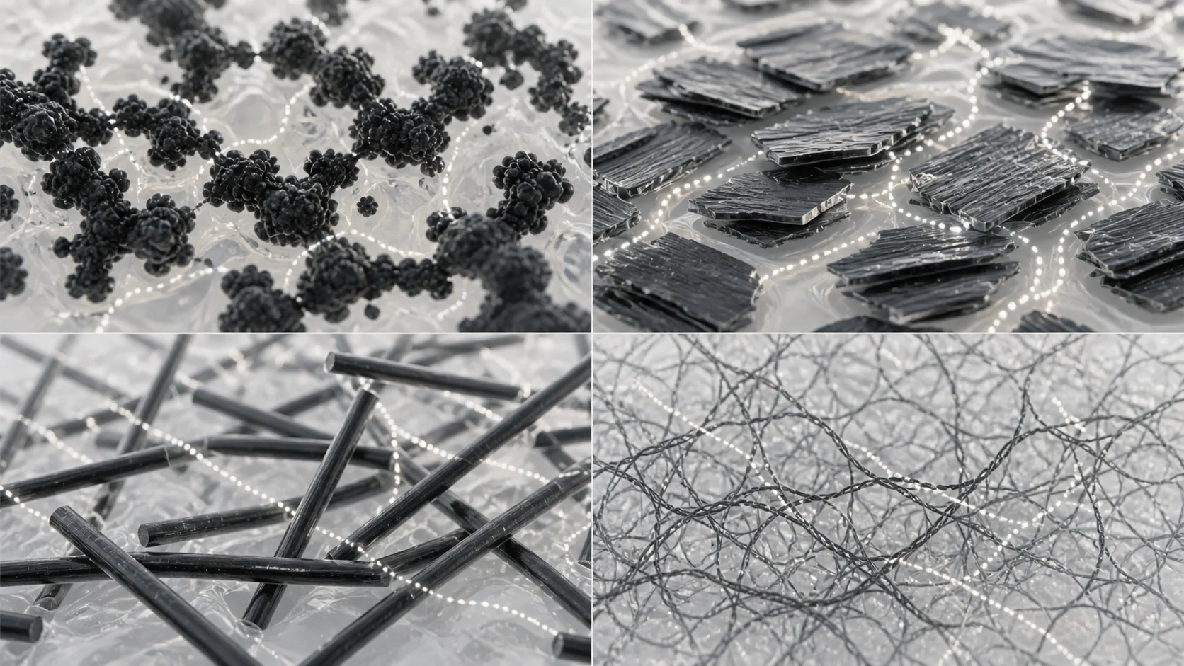
Carbon black, graphite, carbon fiber and carbon nanotubes are all carbon-based conductive fillers, yet their particle shape and network behavior are very different. A low-cost tray, a glossy electronic housing, a sliding gear and a structural EMI shield cannot be solved by the same filler logic.
| Filler type | Particle geometry | Aspect ratio | Typical percolation threshold (wt%) |
|---|---|---|---|
| Carbon black | 0D spherical / aggregate | Around 1 | 10-20% |
| Graphite | 2D platelet | 10-100 | 15-25% |
| Carbon fiber | 1D cylindrical fiber | 50-500 | 8-15% |
| CNT | 1D tubular network | 100-1,000+ | 1-5% |
Percolation threshold and particle geometry
Conductive plastic does not become conductive gradually in a straight line. Once enough filler particles contact, overlap or tunnel close to each other, a continuous pathway forms. This point is the percolation threshold. A lower threshold usually allows better toughness, smoother surface and easier molding because less filler is needed.
Geometry explains most of the difference. Carbon black relies on aggregate chains and electron hopping. Graphite relies on platelet contact. Carbon fiber creates long fiber-to-fiber bridges, but flow alignment can make conductivity directional. CNT can create a three-dimensional conductive network at very low loading, but dispersion quality is critical.
| Property | Carbon black | Graphite | Carbon fiber | CNT |
|---|---|---|---|---|
| Dimensionality | 0D | 2D | 1D | 1D |
| Aspect ratio | Around 1 | 10-100 | 50-500 | 100-1,000+ |
| Typical loading | 15-30% | 20-40% | 10-20% | 2-5% |
| Percolation threshold | 10-20% | 15-25% | 8-15% | 1-5% |
| Surface resistivity | 10^6-10^9 ohm/sq | 10^6-10^9 ohm/sq | 10^2-10^6 ohm/sq | 10^3-10^7 ohm/sq |
| Conductivity mechanism | Electron hopping / tunneling | Platelet face-to-face contact | Fiber-to-fiber contact | Three-dimensional nano-network |
| Anisotropy | Low | Moderate | High | Low to moderate |
| Tensile effect | Down 10-30% | Down 10-20% | Up 10-30% | Preserved or slight increase |
| Flexural effect | Up 30-50% | Slight increase | Up 200-300% | Moderate increase |
| Impact effect | Down 40-60% | Down 30-50% | Down 50-70% | Down 20-30% |
| Elongation effect | Down 70-90% | Down 50-70% | Down 90-95% | Down 40-60% |
| Color | Uniform black | Dark gray / black | Dark gray / black | Deep black |
| Surface gloss | 40-55 | 20-35 | 15-25 | 50-70 |
| Surface roughness | Moderate | Moderate | High | Low |
| Filler visibility | Low on textured parts | Moderate flakes | High fiber bundles | Very low nanoscale visibility |
| Flow reduction | Significant | Moderate | Most significant | Least significant |
| Drying requirement | Usually no | Usually no | Often 2-4 h depending on resin | Usually no; resin rules apply |
| Typical mold temperature | 40-60 C | 40-60 C | 60-80 C | 40-60 C |
| Relative cost | $ | $$ | $$$ | $$$$ |
| Cost per finished part | Low | Low to moderate | Moderate to high | Moderate when low loading reduces scrap |
Carbon black: cost-effective workhorse
Carbon black is usually the first route considered for static dissipative and moderate conductive plastics. It is widely available, stable, easy to source and cost-effective for trays, ESD packaging, conductive profiles, work surfaces, conveyor parts and many black industrial components.
Its limitation is loading. To build a reliable network, carbon black often needs 15-30% addition, depending on structure and resin. That can reduce impact strength, elongation and melt flow. For high-gloss housings or thin-wall parts, a pure carbon-black route may meet resistance but fail appearance or molding requirements.
Graphite: conductive plus lubricious
Graphite is useful when conductivity is only part of the job. Platelet graphite can add lubricity, wear performance and thermal conductivity, so it appears in gears, bearings, sliding contacts and mechanical components.
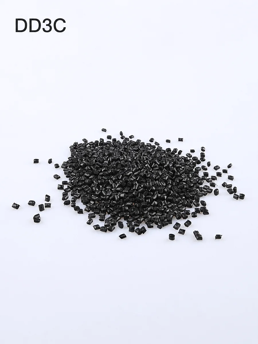
Compared with carbon fiber and CNT, graphite normally gives moderate electrical performance. It can also create a dark gray or metallic surface character. For an existing product reference in a graphite conductive ABS route, see DGK-ABS DD3C graphite conductive ABS.
Carbon fiber: structural conductive reinforcement
Carbon fiber is selected when conductivity and reinforcement must be solved together. It can raise flexural modulus dramatically and improve tensile strength, which is valuable for EMI shielding housings, automotive structural ESD parts, aerospace fixtures and load-bearing conductive components.
The trade-offs are anisotropy, surface appearance and impact. Fibers orient along flow, so resistance can differ between flow and transverse directions. Fiber streaks can be visible on glossy surfaces, and notched impact often drops strongly. Gate design and real-part resistance mapping are required before production approval.
CNT: high-performance low-loading route
CNT is the premium route when low loading, smooth surface, higher impact retention and dimensional stability are important. Because the aspect ratio is very high, a conductive network can form at 2-5% loading in many systems.
The cost per kilogram is high, and dispersion is technically demanding. However, in precision housings, medical device parts, sensors, actuators and high-end ESD components, CNT can reduce scrap, preserve surface quality and keep flow better than high-loading routes. The right comparison is often cost per finished part, not only compound price per kilogram.
Customer scenario: handheld electronic tester housing
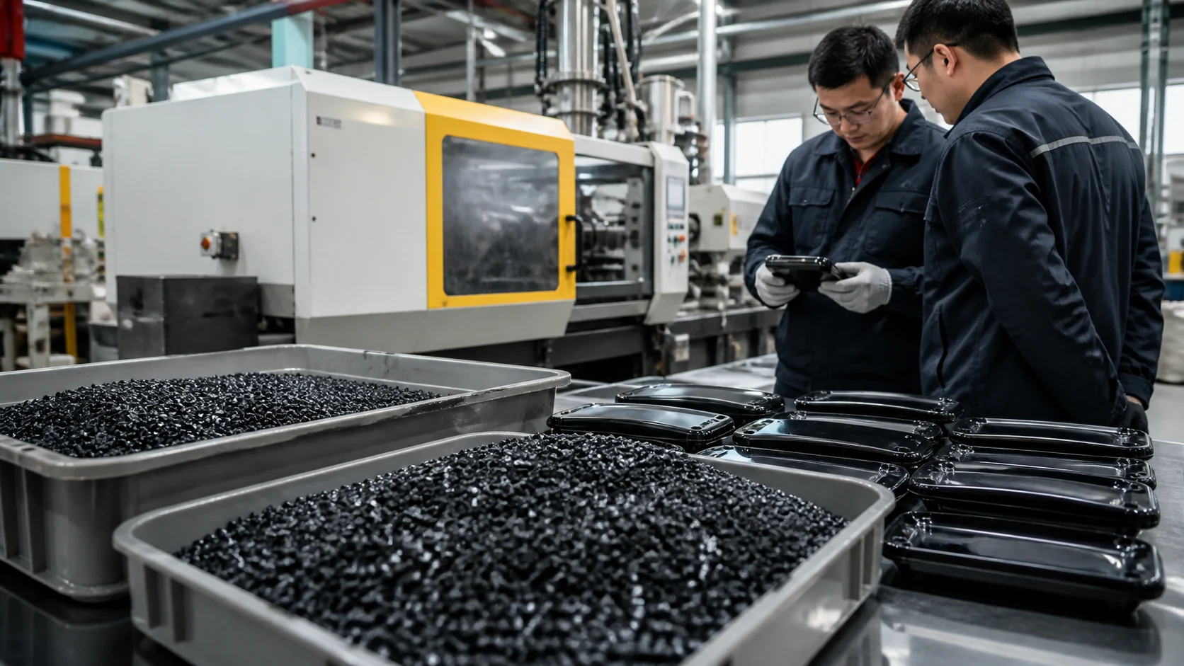
A manufacturer of electronic testing equipment was developing a handheld tester housing. The housing needed surface resistivity in the 10^6-10^8 ohm/sq range, notched Izod impact above 6 kJ/m2, a smooth high-gloss display-facing area and compound cost below about 8 USD/kg.
The first 12% carbon-fiber ABS trial reached the conductivity target, but the surface showed visible fiber streaks and the impact result was only 4.8 kJ/m2. DEYU compared carbon black ABS, CNT ABS and a carbon black plus carbon fiber hybrid route using molded housings rather than only plaques.
| Decision step | Engineering question | Typical output |
|---|---|---|
| 1. Conductivity target | Surface resistance, volume resistivity, static dissipative or conductive? | Target range and test method |
| 2. Mechanical requirement | Impact, tensile, flexural modulus, elongation or wear? | Route that does not over-sacrifice key property |
| 3. Processing constraint | Injection, extrusion, wall thickness, flow length and gate plan? | Flow and anisotropy risk level |
| 4. Surface appearance | Textured black, high gloss, visible part or hidden part? | Acceptable filler visibility and roughness |
| 5. Cost model | Cost per kg or cost per accepted part? | Commercially realistic route |
| 6. Production validation | Can molded parts confirm resistance and defects? | Final material approval evidence |
| Trial parameter | Target / condition |
|---|---|
| Trial quantity | 300 housings across 5 molding cycles |
| Monthly production | 50,000 housings |
| Target surface resistivity | 10^6-10^8 ohm/sq |
| Target notched Izod impact | >6 kJ/m2 |
| Target surface gloss | >60 |
| Compound cost target | <8.00 USD/kg |
| Trial route | Surface resistivity | Impact (kJ/m2) | Gloss | Fiber streaks | Scrap rate | Cost (USD/kg) |
|---|---|---|---|---|---|---|
| Existing 12% carbon fiber ABS | 3 x 10^6 ohm/sq | 4.8 | 22 | Yes | 6.5% | 7.80 |
| DEYU A: 18% carbon black ABS | 4 x 10^7 ohm/sq | 5.2 | 48 | No | 5.0% | 5.20 |
| DEYU B: 3% CNT ABS | 2 x 10^6 ohm/sq | 7.2 | 68 | No | 3.2% | 12.50 |
| DEYU C: carbon black 12% + carbon fiber 3% | 3 x 10^7 ohm/sq | 6.5 | 52 | No | 4.0% | 8.20 |
| Target | 10^6-10^8 ohm/sq | >6 | >60 | No | Lower is better | <8.00 |
How DEYU read the trial result
The CNT route delivered the best technical surface and impact data, but it exceeded the cost target. The carbon black route reduced cost but still missed the impact and gloss targets. The hybrid route was the best balance: it reached the required resistance, improved impact above the threshold and removed fiber streaks, while cost stayed close enough for production negotiation.
DEYU recommended production validation with adjusted gate location and a larger batch, because even a balanced filler system can shift when flow length, weld line position and holding pressure change.
Application fit by filler route
Same theme does not mean same answer. The table below shows typical starting routes; final grade selection still depends on resin, molding method and test standard.
| Application | Recommended starting route | Reason |
|---|---|---|
| IC handling trays and packaging | Carbon black | Cost-effective and uniform black appearance |
| EMI shielding housings | Carbon fiber | Reinforcement plus high conductivity |
| Gears, bearings and sliding parts | Graphite | Lubricity, wear support and moderate conductivity |
| Medical device housings | CNT or hybrid | Surface finish, impact retention and low loading |
| Automotive under-hood parts | Carbon fiber in PA66 | Heat resistance plus mechanical strength |
| Conductive tubing and profiles | Carbon black | Good extrusion practicality and uniform output |
| Precision mechanical components | CNT or hybrid | Dimensional stability and low shrinkage |
| Consumer electronics housings | Hybrid or CNT | Surface appearance plus conductivity |
| ESD flooring and work surfaces | Carbon black | Large-area cost control |
Conclusion
Carbon black, graphite, carbon fiber and CNT are not interchangeable labels. They are different conductive routes with different percolation thresholds, particle geometry, surface behavior, mechanical trade-offs, processing windows and cost logic.
For cost-sensitive static dissipative parts, carbon black is often the starting point. For sliding or thermal applications, graphite deserves attention. For structural conductive parts, carbon fiber is practical. For high-end glossy or precision components, CNT or a hybrid route may be the right answer. DEYU can compare these routes using the customer resin, part drawing, target resistance, mechanical requirement and production validation plan.