Carbon Nanotubes vs. Carbon Fiber in Conductive Plastics: Advantages, Limitations and DEYU Practical Experience
In the development of conductive and anti-static plastics, carbon-based fillers are among the most common technical routes. Typical systems include conductive carbon black, graphite, carbon nanotubes, carbon fiber, graphene and hybrid conductive filler systems.
Buyer and engineer FAQ
Questions engineers often ask about this material route
Where can ABS / PA / POM / PP with a conductive plastic requirement be used?
Typical fields include ESD trays, electronic housings, fixtures, EMI parts and antistatic logistics parts. For this article, DEYU would first confirm the working environment, wall thickness, expected lifetime and whether Conductive Plastics, DGK-PA66 CF15L-CF40L Carbon Fiber PA66 matches the part geometry or needs formulation adjustment.
What are the main performance indicators for the "conductive plastic" target on ABS / PA / POM / PP?
Focus on surface resistance, volume resistance, dispersion uniformity, impact strength and molding stability. Buyers should ask for data on molded parts, not only pellet data, because gate position, filler orientation and thickness can change the final value.
What should engineers watch during injection molding or processing?
For ABS / PA / POM / PP, a practical starting window is 210-245°C melt / 50-80°C mold. Avoid excessive filler loading, control weld lines and verify resistance on the molded part. Final parameters should follow part thickness, gate design and the actual machine.
What details help DEYU recommend Conductive Plastics, DGK-PA66 CF15L-CF40L Carbon Fiber PA66 more accurately?
Send the current resin or grade, drawing or photo, wall thickness, annual quantity, target standard, failure mode and required color. If a reference grade already passed one test but failed in production, include both data sets.
For a precise recommendation, share the part drawing, base resin, target performance, processing method and test standard with DEYU.
1. Background / Problem
In the development of conductive and anti-static plastics, carbon-based fillers are among the most common technical routes. Typical systems include conductive carbon black, graphite, carbon nanotubes, carbon fiber, graphene and hybrid conductive filler systems.
Conductive Plastics and DGK-PA66 CF15L-CF40L Carbon Fiber PA66. Use the conductive plastics category to compare carbon-based conductive routes, and use DGK-PA66 CF15L-CF40L as a structural carbon fiber reinforced reference.
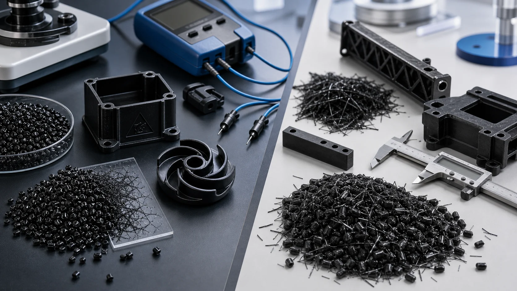
Among them, carbon nanotubes, or CNTs, and carbon fiber, or CF, are often compared by customers. Both can give plastics a certain level of electrical conductivity, but their engineering logic is different.
A simple way to understand the difference is this: carbon nanotubes are mainly used to build a microscopic conductive network, while carbon fiber is mainly used for structural reinforcement with conductive support.
If the comparison only focuses on which filler is more conductive, several important engineering questions may be missed. Does the part also need high stiffness? Is a smooth surface required? Is the part thin-walled or precision molded? Can the surface accept visible fiber texture? Is the target anti-static, static dissipative, conductive, EMI shielding or structural reinforcement?
Therefore, carbon nanotubes and carbon fiber are not simply interchangeable. They represent two different conductive modification routes.
2. Core Differences Between Carbon Nanotubes and Carbon Fiber
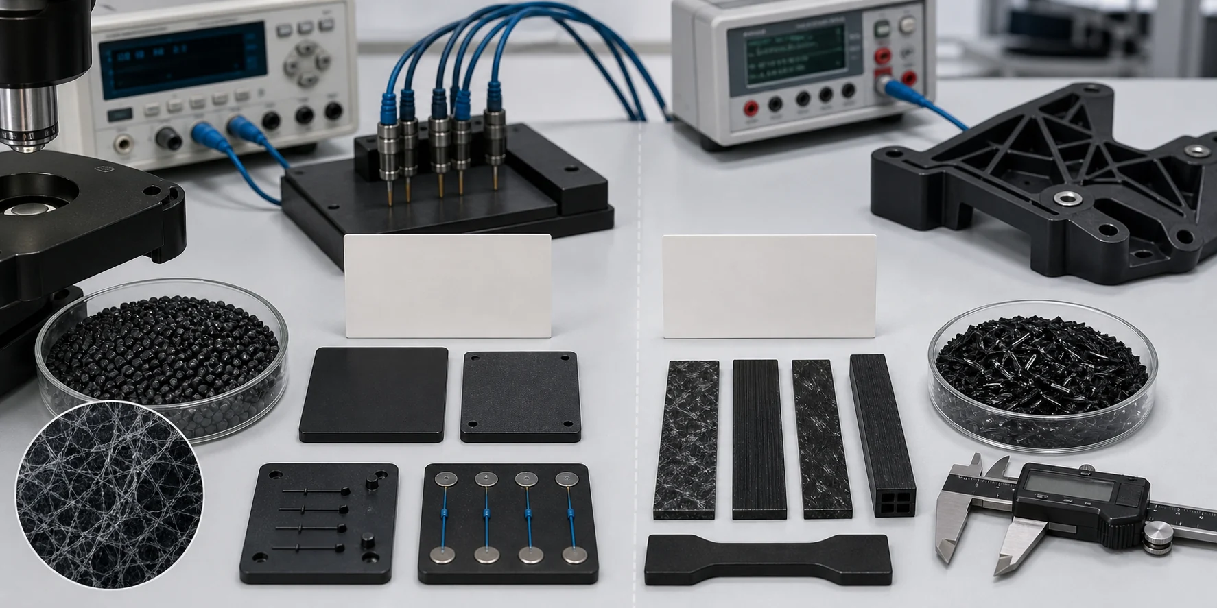
| Comparison Item | Carbon Nanotubes / CNT | Carbon Fiber / CF |
|---|---|---|
| Main function | Builds a microscopic conductive network | Provides structural reinforcement and conductive pathways |
| Filler loading | Often forms a conductive network at relatively low loading | Usually requires higher loading to form continuous conductive paths |
| Mechanical effect | Can maintain toughness and conductivity at lower loading | Significantly improves stiffness, strength and dimensional stability |
| Surface appearance | Easier to achieve a finer surface when well dispersed | May show fiber exposure, flow marks or fiber orientation texture |
| Conductive uniformity | Depends heavily on CNT dispersion and network stability | Affected by fiber length, orientation, wall thickness and flow direction |
| Processing difficulty | Dispersion, agglomeration control and shear stability | Fiber length retention, orientation, mold wear and warpage |
| Color | Usually black or dark | Usually black or dark |
| Typical advantage | Low loading, fine surface and good resistance adjustment range | High stiffness, high strength and lightweight structural support |
| Typical limitation | Difficult dispersion, higher cost and strong formulation know-how required | Higher loading, rougher surface, lower impact toughness and higher processing wear |
| Suitable applications | ESD parts, anti-static parts, precision conductive components and parts requiring better surface finish | Structural conductive parts, reinforced brackets, lightweight housings and shielding structures |
3. Advantages and Challenges of Carbon Nanotube Conductive Plastics
Carbon nanotubes have an extremely high aspect ratio and can form a continuous microscopic conductive network inside a polymer matrix. Compared with conventional conductive carbon black, CNTs can sometimes achieve stable conductive or static dissipative performance at a lower addition level.
Main advantages include conductive network formation at lower filler loading, better suitability for precision injection-molded parts, finer surface appearance, good adjustment space for medium-to-high resistance ranges such as 10^3-10^9 ohm, and compatibility with hybrid conductive systems.
The real challenge of CNT compounds is not whether they can conduct electricity. The challenge is whether they can be well dispersed and remain consistent from batch to batch.
| Technical Challenge | Engineering Impact |
|---|---|
| CNT agglomeration | May cause resistance fluctuation, black spots, rough surface and local instability |
| Narrow dispersion window | Insufficient shear cannot break agglomerates; excessive shear may affect the conductive network |
| High resin compatibility requirement | CNT dispersion and resistance behavior vary greatly in different resin systems |
| Process-sensitive resistance | Injection temperature, screw shear, holding pressure, wall thickness and flow path may affect the network |
| Higher cost than conductive carbon black | Value should be reflected through lower loading and better performance consistency |
| Multi-point testing required | Single-point resistance cannot represent the electrical consistency of the whole part |
For this reason, CNT composite materials strongly depend on supplier formulation know-how, dispersion technology, twin-screw compounding control and application-side troubleshooting experience.
4. Advantages and Challenges of Carbon Fiber Conductive Plastics
Carbon fiber provides both reinforcement and conductivity in modified plastics. In many applications, its value is not only conductivity, but also improved stiffness, strength, heat resistance and dimensional stability.
Main advantages include significant improvement in stiffness and strength, conductivity and reinforcement in one material route, better dimensional stability direction and suitability for structural conductive parts.
The main difficulties of carbon fiber compounds are fiber orientation, surface appearance, impact toughness and processing wear.
| Technical Challenge | Engineering Impact |
|---|---|
| Strong fiber orientation | Electrical and mechanical properties may differ by direction |
| Possible fiber exposure | May not be suitable for high-appearance surfaces, precision surfaces or sliding surfaces |
| Possible impact toughness reduction | Higher stiffness may come with increased brittleness |
| Weld line strength risk | Fiber orientation around weld lines can affect part strength |
| Higher mold and screw wear | Equipment durability and long-term processing cost should be considered |
| More difficult thin-wall filling | High fiber loading may increase melt flow resistance and filling pressure |
Therefore, carbon fiber is more suitable for structural parts, reinforced components and functional housings. It may not be the best route for every part requiring a fine surface, high toughness or highly uniform electrical resistance.
5. How to Choose Between CNT and Carbon Fiber
5.1 When to Consider Carbon Nanotubes First
A CNT-based route should be considered first when the customer needs stable static dissipative or conductive performance, target resistance at relatively low filler loading, precision injection molding, small parts or thin-wall structures, better surface smoothness, less stiffness increase and customized conductivity in POM, PA, PP, ABS or other resin systems.
Typical applications include conductive POM gears, sliders and precision components, anti-static or conductive electronic trays, ESD injection-molded housings, sensor housings, dust-control anti-static parts and precision conductive plastic components.
5.2 When to Consider Carbon Fiber First
A carbon fiber route should be considered first when the customer needs high stiffness, high strength, lightweight structure, structural brackets, housings or load-bearing components, dimensional stability and acceptance of black appearance or possible fiber texture.
Typical applications include carbon fiber reinforced PA66 structural parts, carbon fiber reinforced PP brackets, carbon fiber reinforced ABS housings, conductive reinforced brackets, lightweight components, EMI or static-control housings and high-stiffness electrical components.
6. Route Suggestions for Different Resin Systems
| Base Resin | CNT Route Suitable Direction | Carbon Fiber Route Suitable Direction |
|---|---|---|
| POM | Precision conductive parts, wear-resistant conductive parts and low-resistance-fluctuation components | High-stiffness sliding structural parts, with mating surface and fiber exposure checked |
| PA6 / PA66 | ESD, anti-static and conductive precision parts; can also work with hybrid systems | High-strength, high-stiffness and lightweight structural parts |
| PP | Conductive trays, ESD packaging and conductive structural components | Lightweight brackets and reinforced conductive PP parts |
| ABS | Anti-static housings, conductive housings and black products with better surface requirements | High-stiffness housings and functional support parts |
| PC / PC-ABS | ESD housings and electrical structural parts | High-stiffness and shielding-oriented structural parts |
| TPU / TPE | Flexible conductive parts, anti-static films or elastic components | Carbon fiber is less common in high-flexibility applications and needs careful validation |
7. DEYU Practical Experience in Carbon Nanotube Composite Materials
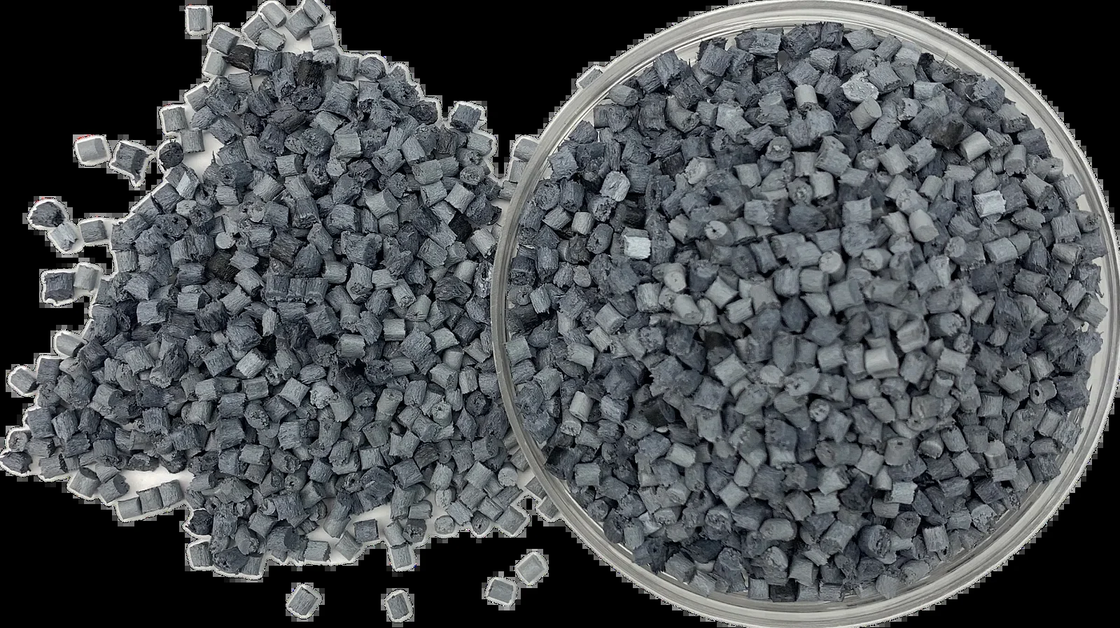
DEYU has long-term application development experience in conductive, anti-static and carbon-based composite materials. In particular, DEYU has accumulated practical experience in carbon nanotube composite materials, including formulation adjustment, dispersion control, injection molding validation and customer application troubleshooting.
DEYU CNT systems are not limited to laboratory formulations. They are developed around real customer parts and production requirements, including CNT dispersion control in different resin systems, surface and volume resistance adjustment, post-molding resistance stability validation, multi-point resistance testing, resistance differences between thin-wall and thick-wall areas, and the influence of molding temperature, holding pressure and gate location on the conductive network.
For specific resin systems, DEYU can provide CNT or hybrid conductive solutions based on POM, PA, PP, ABS and other materials. For example, a CNT conductive POM direction can be evaluated for precision conductive products requiring surface quality, toughness and resistance stability. In nylon systems, DEYU can also combine carbon fiber reinforcement with specialized conductive routes to balance structure and electrical performance.
| DEYU Support Area | Practical Value for Customers |
|---|---|
| CNT dispersion experience | Reduces agglomeration, black spots and resistance fluctuation risk |
| Multi-resin conductive development | Allows route adjustment for POM, PA, PP, ABS and other resin systems |
| Injection molding process support | Helps explain how temperature, pressure, gate position and wall thickness affect resistance |
| Small-batch sample validation | Supports faster confirmation in real product trials |
| Custom resistance range | Formulation can be adjusted for anti-static, static dissipative or conductive targets |
| Multi-function development | Supports conductivity plus wear resistance, reinforcement or flame retardancy |
| Application-side problem analysis | Helps optimize resistance drift, surface roughness, toughness loss and molding difficulty |
8. Reference Product Data Structure
| Item | CNT Conductive Compound Direction | Carbon Fiber Conductive Compound Direction |
|---|---|---|
| Product direction | DGK carbon nanotube conductive composite | DGK carbon fiber reinforced conductive composite |
| Base resin | POM / PA / PP / ABS / PC-ABS / TPU | PA / PP / ABS / PC-ABS / POM |
| Modification route | CNT / CNT + carbon black / CNT hybrid conductive system | Chopped carbon fiber / carbon fiber + conductive filler |
| Main function | Conductive, anti-static, static dissipative and resistance stability | Reinforcement, lightweighting, conductivity and dimensional stability |
| Processing method | Injection molding / extrusion / cast film / sheet extrusion, depending on resin | Injection molding / extrusion, mainly structural parts |
| Color | Mainly black or dark color | Mainly black or dark color |
| Surface resistance | Typically selected around 10^3-10^9 ohm according to target | Selected according to conductivity and structural requirement |
| Surface appearance | More suitable for fine surface direction | Fiber exposure, texture and flow marks should be checked |
| Conductive uniformity | Depends on CNT dispersion and molding stability | Affected by fiber orientation, wall thickness and flow direction |
| Typical applications | ESD precision parts, conductive POM, conductive housings, electronic trays and dust-control anti-static parts | Structural reinforced parts, conductive brackets, lightweight components and shielding housings |
9. DEYU Internal Customer Application Validation Data
The following content is an anonymized validation structure based on practical material development logic. Customer name, product model and non-public report details are not disclosed.
9.1 Original Application Data
A precision electronic structural component customer originally used conductive carbon black filled POM for a small conductive sliding part. The material could reach the basic conductive range, but after injection molding the customer observed local resistance fluctuation, reduced surface gloss and insufficient toughness in small-size parts.
| Original Item | Customer Application Data |
|---|---|
| Application | Small precision conductive sliding part / electronic structural component |
| Original material | Conductive carbon black filled POM |
| Main wall thickness | 1.2-2.0 mm |
| Target surface resistance | 10^4-10^6 ohm |
| Original resistance fluctuation | 1-2 orders of magnitude |
| Surface gloss feedback | Noticeable gloss reduction |
| Injection scrap rate | 4-6% |
| Assembly feedback issue rate | 5-8% |
| Part cracking or brittleness feedback | 2-4% |
| Monthly usage | 20,000-50,000 pieces |
| Customer target | Stabilize the conductive range while improving surface smoothness, toughness and injection consistency |
9.2 DEYU Debugging Direction
Based on the customer's part size, target resistance and surface requirement, DEYU adjusted the original single conductive carbon black route toward a CNT hybrid conductive system. The goal was not simply to lower resistance, but to improve conductive network stability, surface smoothness and post-molding batch consistency within the target range.
| Debugging Parameter | Original Direction | DEYU Adjustment Direction |
|---|---|---|
| Material route | Conductive carbon black POM | CNT hybrid conductive POM direction |
| Conductive system | High-loading conductive carbon black | Carbon nanotube + hybrid conductive system |
| Target resistance | 10^4-10^6 ohm | Stable 10^4-10^6 ohm range |
| Filler loading | Higher filler loading direction | Lower loading and higher conductive-network efficiency |
| Surface appearance | Black but insufficient surface smoothness | Improved gloss and surface uniformity |
| Toughness balance | High carbon black loading affected toughness | CNT low-loading route supported better toughness retention |
| Validation method | Single-point resistance + appearance | Multi-point resistance + appearance + toughness + scrap rate + assembly feedback |
9.3 Trial Result Direction
| Validation Item | Original Data | DEYU Trial Direction | Engineering Interpretation |
|---|---|---|---|
| Surface resistance | 10^4-10^6 ohm, with local fluctuation | 10^4-10^6 ohm with improved consistency | CNT hybrid system helped stabilize the conductive network |
| Resistance fluctuation | 1-2 orders of magnitude | Within 1 order of magnitude | Multi-point resistance fluctuation decreased |
| Surface gloss feedback | Noticeable gloss reduction | Improved surface smoothness | Lower loading reduced rough-surface tendency |
| Injection scrap rate | 4-6% | 2-3% | Improved flow and dispersion supported molding consistency |
| Assembly feedback issue rate | 5-8% | 2-4% | Better dimensional and toughness balance supported assembly |
| Cracking or brittleness feedback | 2-4% | 1-2% | Lower-loading conductive system supported toughness retention |
For small conductive POM parts, precision sliding components, electronic structural parts and conductive products with surface quality requirements, this CNT hybrid route is more suitable for evaluation than a purely high-loading carbon black system.
10. What Information Should Buyers Provide?
| Buyer Input | Why It Matters |
|---|---|
| Target function | Anti-static, static dissipative, conductive, shielding or structural reinforcement determines the filler route |
| Target resistance range | 10^3, 10^6 and 10^9 ohm targets require different formulation designs |
| Base resin | POM, PA, PP, ABS, PC-ABS and TPU interact differently with CNT and CF |
| Part drawing | Wall thickness, ribs, gate location and flow length affect resistance and fiber orientation |
| Surface requirement | Gloss, matte finish, blackness and smoothness determine whether carbon fiber is suitable |
| Mechanical requirement | High stiffness, high toughness, impact resistance or dimensional stability affect route selection |
| Current problem data | Resistance fluctuation, rough surface, brittleness, warpage, fiber exposure and scrap rate guide optimization |
| Processing method | Injection molding, extrusion, cast film or sheet processing require different flow designs |
| Mating part information | If sliding friction is involved, the metal or plastic mating material should be confirmed |
| Monthly usage and cost target | Determines the feasibility of CNT, CF or hybrid conductive systems |
11. Conclusion
Carbon nanotubes and carbon fiber are both important carbon-based conductive modification routes, but their engineering positions are different.
Carbon nanotubes are better suited for building low-loading, more uniform and finer-surface conductive networks. Carbon fiber is better suited for parts that require structural reinforcement, lightweighting and conductive support at the same time.
If the customer focuses on resistance stability, surface smoothness, precision injection molding, toughness retention and low-loading conductivity, a CNT hybrid system is usually worth evaluating first.
If the customer focuses on high stiffness, high strength, dimensional stability and structural load-bearing, a carbon fiber reinforced conductive system may offer greater advantages.
DEYU can support conductive, anti-static, static dissipative and multifunctional material development based on POM, PA, PP, ABS, TPU and other resin systems through formulation design, CNT dispersion control, injection molding support, multi-point resistance testing and customer application validation.