
Conductive Plastic Extrusion: PC Sheet and Flame-Retardant Conductive PP Sheet Case Notes
Conductive plastic extrusion behaves differently from injection molding. A compound that works in molded parts can still show sheet defects, resistance anisotropy and die buildup once it runs through a T-die line.
Conductive extrusion FAQ
Conductive Plastic Extrusion: PC Sheet and Flame-Retardant Conductive PP Sheet Case Notes
Why can an injection-grade conductive compound fail during extrusion?
Injection molding is mainly shear flow, while sheet extrusion adds long residence time, die flow and elongational flow. Conductive filler can orient, agglomerates can print through the sheet, and the conductive network can become direction-dependent.
Is DGK-PC DD5-7JC a public standard product page?
No. In this article it is treated as a custom extrusion project direction for conductive PC sheet. Public PC pages on the site are used only as base-resin references.
Which public product is the closest reference for the PP case?
DGK-PP DD4-5A-JC is the closest public flame-retardant conductive PP reference. DGK-PP DD4-5FR-JC in this article remains a project validation direction.
What information should be sent before an extrusion trial?
Send sheet thickness, die type, screw configuration, drying condition, extrusion temperature profile, resistance target, surface defect photos, required UL94 thickness and expected line speed.
Conductive PC extrusion sheet: from daily firefighting to 12-hour stable running
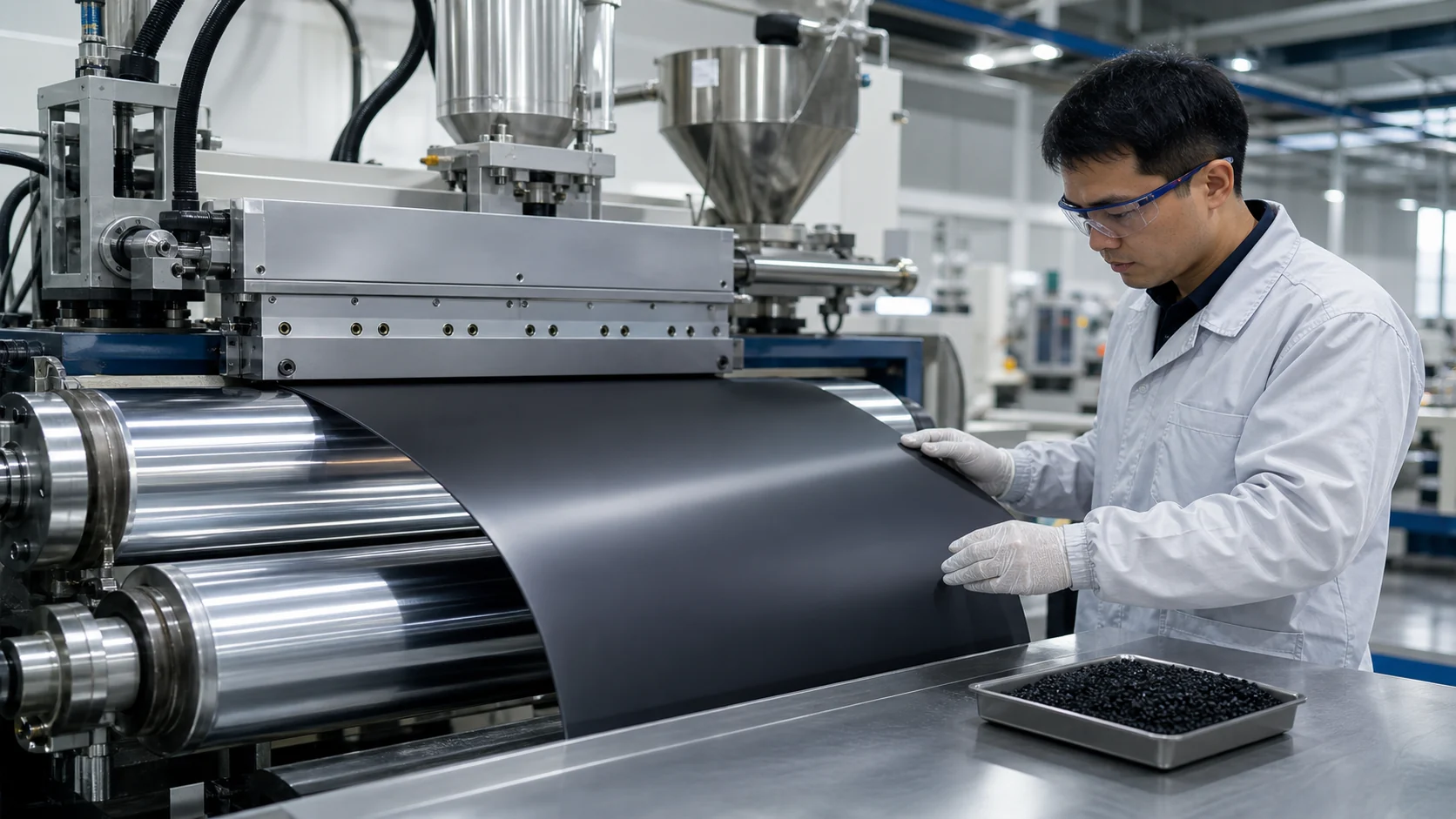
People who run conductive plastic extrusion know the pattern: molded parts look fine, but the same material becomes difficult on an extrusion line. Surface resistance moves up and down, the sheet shows small specks, and the die has to stop for carbon cleaning before the shift plan is finished.
Two recent material directions have been comparatively smooth in production. The data below are line records and project validation data, shared as engineering reference rather than universal guaranteed values.
One carrier-tape sheet line previously used another conductive PC. The main issue was surface quality. Carbon-black agglomerates formed crystal-like specks at about 5-8 points per square meter, and the forming yield stayed near 85%. The more serious issue was resistance anisotropy: the machine direction measured about 3x10^6 ohm, while the transverse direction could reach 2x10^8 ohm.
Several peers gave the same diagnosis: carbon-black agglomerate size was beyond what the T-die could tolerate, and the screw configuration did not provide enough second-stage dispersion. Temperature, screw speed and die gap adjustments helped only slightly.
The line then changed to DGK-PC DD5-7JC, a custom conductive PC direction optimized for extrusion. The target surface resistance was kept in the 10^5-10^7 ohm range, and HDT was 124°C at 0.45 MPa, so downstream welding and baking steps were not disturbed.
| Item | Before material change | After DGK-PC DD5-7JC project direction |
|---|---|---|
| Surface specks | 5-8 defects/m2 | < 1 defect/m2 |
| Transverse surface resistance | 2x10^8 ohm | 5x10^6 ohm |
| MD/TD resistance gap | about 2 orders | < 0.5 order |
| Continuous run time | 4-6 h | > 12 h |
| Carrier-tape forming yield | 85% | 96.5% |
The customer reported that the speck problem was basically solved, the matte version matched AOI inspection, MD/TD resistance consistency was much better, and the die could run for more than 12 hours instead of stopping every 4-6 hours. The material has become a standard carrier-tape sheet material for that line, with cumulative purchase above 60 tons.
Processing details from the PC sheet trial
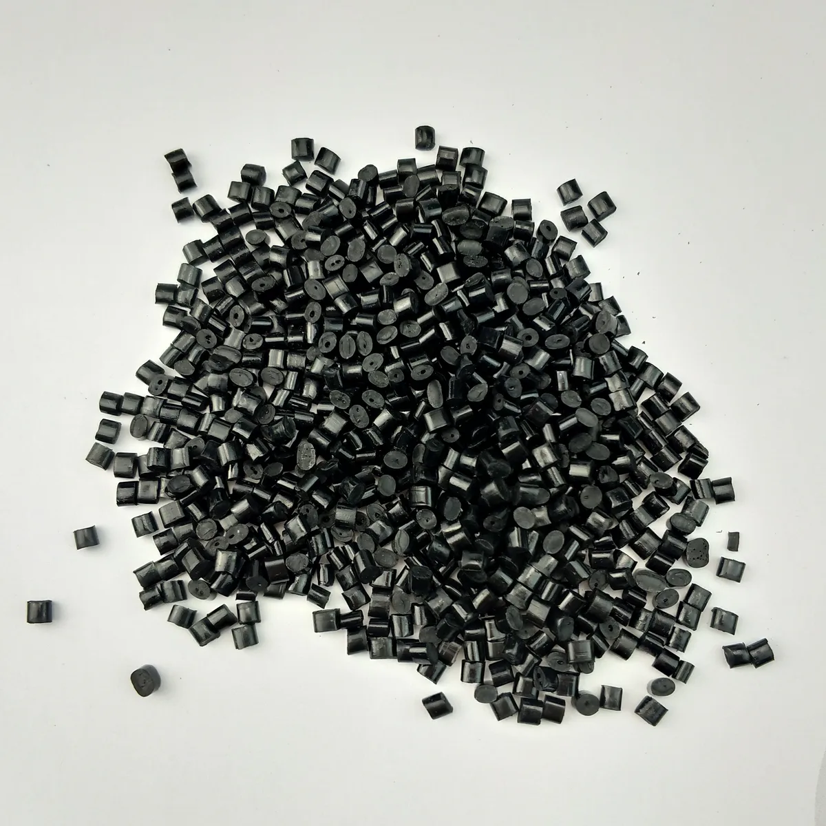
Drying had to be tightened. The old setting was 105°C for 3 hours; the stable window used 110°C for 4.5 hours. If moisture was not fully removed, silver streaks appeared and the surface lost stability.
The die temperature should not be too high. The line moved from 265°C to 260°C. Excess temperature increased melt degradation risk and made carbon-black bleeding or deposit formation more likely.
The mold or roll temperature was raised from 85°C to 90°C. Surface gloss and resistance uniformity improved. The grade can be supplied in matte and glossy versions: matte for AOI-sensitive inspection, glossy for ordinary appearance parts.
Flame-retardant conductive PP extrusion sheet: import replacement direction
Another project was an insulating separator for a battery module. The customer required UL94 V-0 at 3.2 mm and surface resistance no higher than 10^5 ohm. The original halogen flame-retardant PP passed V-0 but was non-conductive, above 10^12 ohm. Conductive coating was tried, but thermal expansion and contraction during battery cycling caused coating peel-off.
DGK-PP DD4-5FR-JC was used as a custom extrusion project direction. The sheet trial recorded surface resistance around 10^4 ohm and UL94 V-0 at 3.2 mm. Because PP has an oxygen index of only about 17-18%, the formula must balance flame retardant loading and conductive carbon black without destroying extrusion stability.
The melt flow rate was 0.4 g/10 min at 230°C / 2.16 kg. This low MFI helped maintain melt strength during sheet extrusion, so the sheet did not collapse easily after leaving the die.
| Comparison | Original FR PP, non-conductive | Imported conductive FR PP | DGK-PP DD4-5FR-JC project direction |
|---|---|---|---|
| Surface resistance | > 10^12 ohm | 10^4-10^5 ohm | 10^4 ohm |
| Flame rating, 3.2 mm | V-0 | V-0 | V-0 |
| Lead time | 2 weeks | 8-10 weeks | 2 weeks |
| Material cost | about RMB 18/kg | about RMB 45/kg | about RMB 25/kg |
The process window was drying at 90°C for 4-5 hours, extrusion temperature 210-225°C and die temperature 80°C. During the first trial, a slightly high line speed caused light flow marks. Reducing speed, stabilizing temperature and pressure, and then increasing speed gradually solved the issue. The customer reported that 10^4 ohm resistance met equipotential requirements, local discharge disappeared, material cost was about 44% lower than the imported option, and lead time dropped from 8-10 weeks to 2 weeks. Five tons have been purchased for pilot-line validation.
Four practical lessons
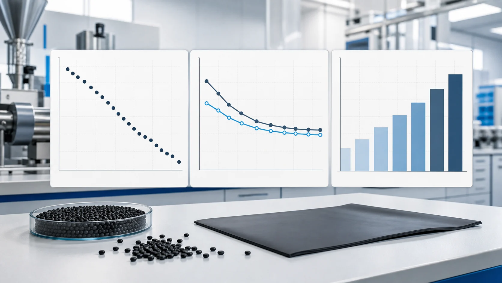
- Injection success does not mean extrusion success. Injection flow is shear-dominant, while extrusion adds elongational flow; conductive filler can orient and the conductive network can be damaged.
- Appearance is often harder than conductivity. Resistance can often be corrected with formulation and process, but specks and agglomerates on carrier tape, tray or chip-contact surfaces can turn one visible point into scrap.
- The process window must be controlled strictly. Drying, extrusion temperature, die temperature and line speed all affect resistance uniformity and surface quality.
- Die carbon buildup deserves attention. Extending continuous run time from 4-6 hours to more than 12 hours directly improves extrusion efficiency.
For the closest public PP reference, see DGK-PP DD4-5A-JC flame-retardant conductive PP. For conductive PC sheet and DGK-PP DD4-5FR-JC, contact DEYU with target thickness and extrusion-line details because these grades are handled as custom project directions.