A CNT-Composite PP Molding Method Above 15 S/cm and Cost-per-kWh Calculation for Flow Battery Bipolar Plates
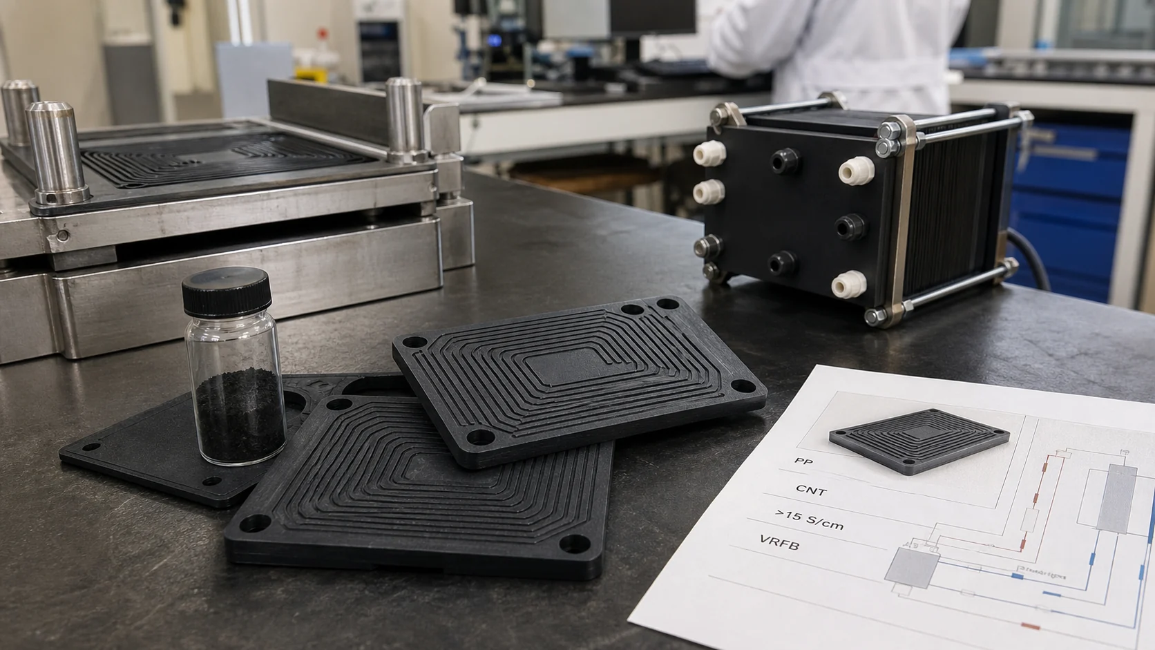
This paper-style solution reframes conductive PP bipolar plate development around two linked questions: how to mold a CNT-composite PP plate above 15 S/cm, and how that plate cost changes the storage cost per kWh in a flow battery stack.
Article FAQ
A CNT-Composite PP Molding Method Above 15 S/cm and Cost-per-kWh Calculation for Flow Battery Bipolar Plates
Why use CNT in PP bipolar plates instead of graphite alone?
CNTs can bridge gaps between graphite particles and improve network continuity at lower incremental loading. Graphite still carries the main conductive framework, but CNTs help through-network conductivity and reduce the need to overfill the PP matrix.
Is >15 S/cm enough for every flow battery bipolar plate?
No. The target depends on stack voltage loss, plate thickness, contact pressure and chemistry. This article uses >15 S/cm as a practical molded-plate target for the described method, not as a universal specification.
Why include cost per kWh in a material article?
Bipolar plates are repeated many times in a stack. Conductivity, scrap rate, molding cycle and plate cost all affect the final storage cost, so material selection should be linked to the stack economic model.
What sample data should be supplied before formulation?
Provide the plate drawing, target conductivity method, compression pressure, electrolyte chemistry, stack cell count, expected kWh and acceptable scrap rate. This allows formulation and cost modeling to be evaluated together.
Abstract
This article proposes a practical molding route for a carbon nanotube (CNT) composite polypropylene plate intended for liquid-flow battery bipolar plate applications. The target is not the lowest coupon resistance in isolation, but a molded plate whose effective conductivity can exceed 15 S/cm while maintaining plate flatness, flow-channel replication and acceptable production economics.
The method is based on three principles: a pre-dispersed CNT masterbatch to avoid local agglomeration, a graphite-assisted conductive skeleton to reduce the CNT dosage required for percolation, and a staged compression or injection-compression molding window that maintains pressure long enough for the highly filled melt to consolidate into thin ribs and flow channels.
1. Research Background
Vanadium redox flow batteries and other liquid-flow battery systems use bipolar plates to collect current, separate positive and negative electrolytes, distribute flow and support stack compression. In many stacks, the bipolar plate is not a small accessory: it is a repeated component, so its unit cost directly affects stack CAPEX and the levelized storage cost.
Graphite plates provide conductivity and corrosion resistance, but they are brittle and costly to machine. Metal plates conduct well, yet need surface protection against corrosion. Conductive polypropylene (PP) composites offer a different route: lower density, moldable flow channels, corrosion resistance and the possibility of high-volume thermoplastic processing.
The trade-off is severe. Conductivity usually requires high carbon loading, while molding quality requires melt flow. A formulation that exceeds 15 S/cm in a compressed plaque may fail if it cannot reproduce a 0.6-1.2 mm channel wall, if it warps after cooling, or if conductive filler scratches the mold excessively.
For a public high-conductive PP reference, see DGK-PP DDL28 high-conductive polypropylene. For comparison with a broader bipolar-plate discussion, see high-conductive PP bipolar plates beyond resistivity.
2. Materials and Molding Method
| Step | Method | Engineering purpose |
|---|---|---|
| 1. Dry blending | PP carrier resin, graphite, conductive carbon black and CNT masterbatch are weighed by target ratio. | Create a carbon skeleton without relying on CNT alone. |
| 2. Twin-screw compounding | Moderate screw speed, staged feeding and vacuum venting reduce CNT agglomeration and moisture residue. | Preserve filler aspect ratio while building network continuity. |
| 3. Sheet or preform preparation | Pellets are molded into a preform sheet or directly fed into injection-compression tooling. | Stabilize dosing and reduce short-shot risk in thin channels. |
| 4. Compression / ICM molding | Dynamic mold temperature and delayed final compression improve channel replication. | Force the highly filled melt into ribs and grooves before solidification. |
| 5. Post-molding stabilization | Flat cooling under controlled pressure and 24 h conditioning before test. | Reduce warpage and stabilize contact resistance readings. |
| Component | Reference range | Function | Risk if excessive |
|---|---|---|---|
| PP matrix | 20-35 wt% | Thermoplastic processability, chemical resistance and toughness | Too low: brittle plate; too high: poor conductivity |
| Graphite / expanded graphite | 45-65 wt% | Main conductive and corrosion-resistant framework | Viscosity rise, plate brittleness, mold abrasion |
| Conductive carbon black | 3-8 wt% | Fills gaps between graphite particles | Dispersion difficulty and impact loss |
| CNT masterbatch | 1-5 wt% active CNT route | Bridges conductive gaps and improves through-network continuity | Agglomeration, cost increase, viscosity spike |
| Coupling / processing aid | 0.5-3 wt% | Improves wetting, flow and demolding | Migration, contact resistance drift if poorly selected |
3. Conductivity and Plate Quality Targets
| Indicator | Target in this method | Why it matters |
|---|---|---|
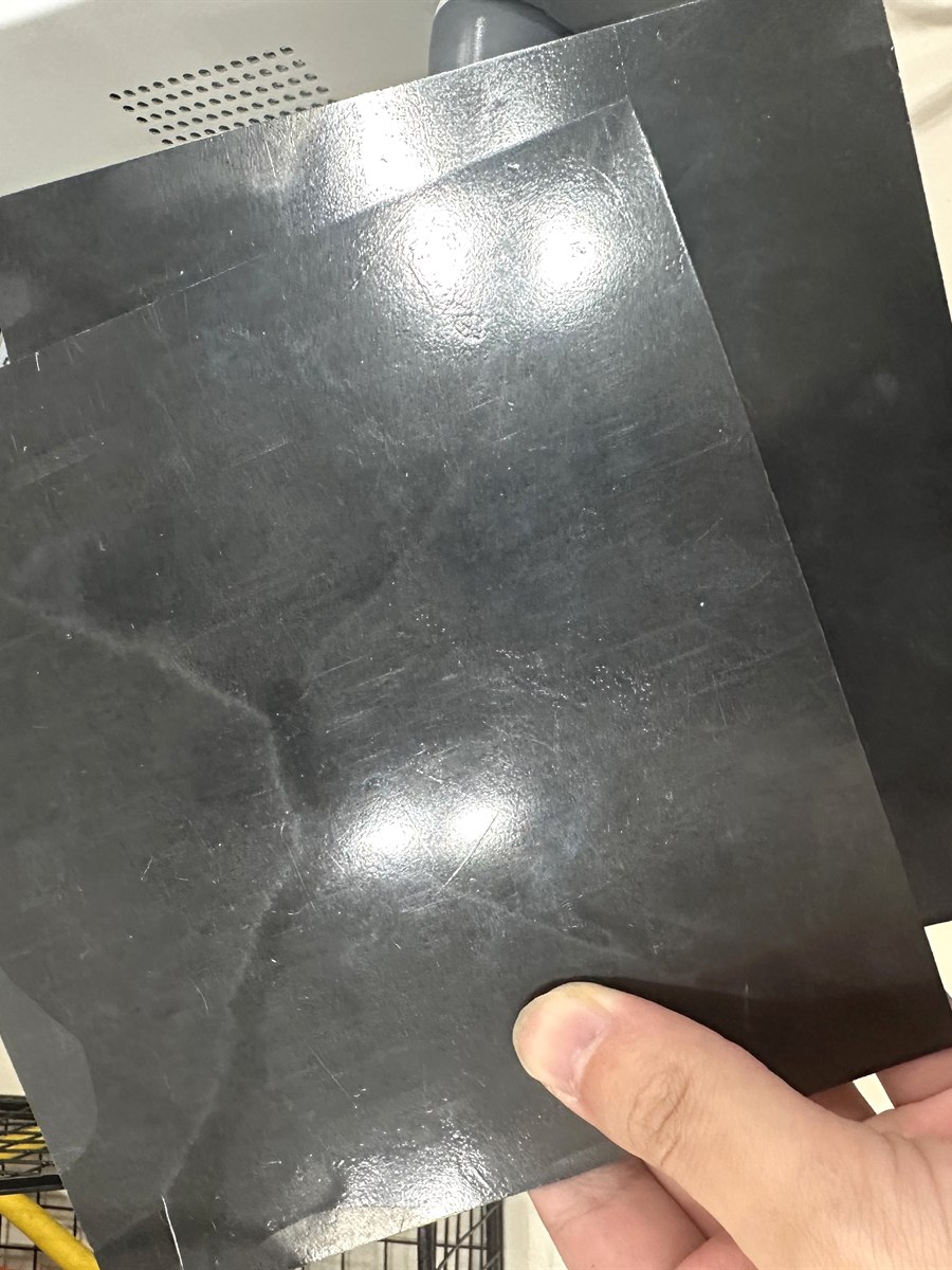
| Effective molded conductivity | >15 S/cm | Minimum practical target for plate-level conductive PP evaluation in this article |
| Through-plane consistency | Coefficient of variation <15% | Stack performance depends on repeatable plate-to-plate contact |
| Plate thickness variation | Within +/-0.03 mm after stable molding | Controls compression uniformity and sealing risk |
| Flow-channel replication | >95% complete rib and groove filling | Affects electrolyte pressure drop and active area utilization |
| Flexural strength | >25 MPa | Basic handling and stack compression requirement |
| Contact resistance | Project-specific, measured under defined compression | More relevant to stack loss than coupon resistivity alone |
4. Application to Flow Battery Bipolar Plates
In a flow battery, every cell pair repeats the same plate architecture. A small reduction in plate cost, scrap rate or thickness can therefore affect the entire stack cost. The CNT-composite PP method is attractive when the project needs molded channels, corrosion resistance and lower part weight, but still requires an electrical pathway strong enough for stack operation.
The method should be evaluated on real plate geometry rather than on small plaques only. A molded bipolar plate has ribs, channels, sealing lands, holes and thickness transitions. These features change carbon orientation, local packing density and contact pressure, which means the relevant number is not simply one resistance point on a flat plaque.
5. Cost-per-kWh Storage Calculation
| Cost item | Symbol | Example assumption | Role in kWh storage cost |
|---|---|---|---|
| Bipolar plate unit cost | C_plate | USD 3.20 per molded plate | Repeated across every cell; sensitive to material yield and cycle time |
| Number of plates per stack | N_plate | 120 pieces | Multiplies the plate cost contribution |
| Stack rated energy | E_stack | 25 kWh | Converts stack component cost into USD/kWh |
| Plate scrap rate | S | 3% after process optimization | Raises effective plate cost if molding is unstable |
| Balance of stack cost | C_other | USD 1,950 | Membrane, frame, electrolyte interface, compression hardware and assembly |
| Calculation step | Formula | Example result |
|---|---|---|
| Effective plate cost | C_plate_eff = C_plate / (1 - S) | 3.20 / 0.97 = USD 3.30 |
| Total plate cost | C_plate_total = C_plate_eff x N_plate | 3.30 x 120 = USD 396 |
| Stack cost | C_stack = C_plate_total + C_other | 396 + 1,950 = USD 2,346 |
| Stack material cost per kWh | C_kWh = C_stack / E_stack | 2,346 / 25 = USD 93.84/kWh |
| Scenario | Conductivity result | Scrap rate | Plate unit cost | Calculated stack material cost |
|---|---|---|---|---|
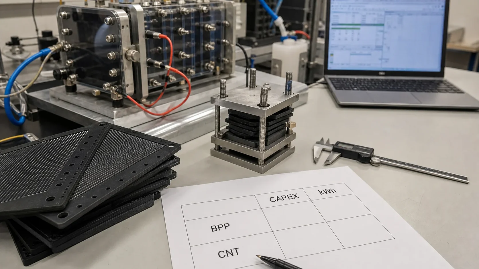
| Graphite-only control | 7-10 S/cm | 15% | USD 2.70 | USD 96.11/kWh |
| CNT-composite PP method | >15 S/cm | 3% | USD 3.20 | USD 93.84/kWh |
| Overfilled high-carbon plate | >20 S/cm | 10% | USD 3.80 | USD 106.27/kWh |
6. Engineering Discussion
The cost table shows why material selection cannot chase conductivity alone. A graphite-only plate may look cheaper per piece, but if conductivity is marginal and scrap is high, the final cost per kWh can be worse. An overfilled plate may achieve a higher S/cm value, but excess filler can raise both raw material cost and molding scrap.
The useful window is therefore a balanced region: CNTs are used as a conductive bridge rather than as a bulk filler, graphite provides the main conductive body, and molding pressure plus temperature history are controlled so the thin channel geometry is fully replicated.
For production validation, DEYU recommends measuring conductivity in at least three zones: inlet/outlet area, central active area and sealing land. The plate should also be tested after compression cycling because real stacks load the plate continuously rather than leaving it as a free-standing coupon.
7. Buyer Validation Checklist
- Target flow battery chemistry: VRFB, zinc-bromine, iron-chromium or another electrolyte system.
- Plate drawing with overall dimensions, channel depth, rib width, sealing land width and hole positions.
- Required conductivity test method: in-plane, through-plane, contact resistance and compression pressure.
- Target stack size: number of cells, expected plate quantity per stack and rated kWh.
- Allowed plate thickness tolerance, flatness requirement and sealing compression window.
- Annual volume and acceptable scrap-rate target for cost-per-kWh calculation.
Conclusion
A CNT-composite PP bipolar plate should be judged as a formed engineering component, not only as a conductive plastic coupon. The proposed route uses a graphite-rich carbon framework, a controlled CNT bridge network and compression or injection-compression molding to target conductivity above 15 S/cm while preserving plate geometry.
When this method is connected to a flow-battery cost model, the important result is not simply the S/cm number. It is the combined effect of conductivity, scrap rate, cycle time, plate unit cost and stack energy. In the example calculation, a slightly higher unit plate cost can still reduce USD/kWh when molding stability and usable conductivity improve.