
How to Solve Surface-Resistance Variation in Multi-Cavity Injection-Molded Antistatic PP: DGK-PP KJD789R-A1
In multi-cavity antistatic PP molding, one shot can produce parts with markedly different surface resistance because every cavity sees a different combination of flow length, shear and cooling. This guide explains how DGK-PP KJD789R-A1 combines a process-tolerant material design with cavity-by-cavity control to keep resistance within the agreed static-dissipative window.

Buyer and engineer FAQ
Questions engineers often ask about this material route
Why can four cavities from the same shot have different resistance?
Each cavity has a different flow length, turn pattern, pressure, shear history and cooling history. Those differences change the orientation and connectivity of the antistatic phase, so resistance must be checked by cavity and by position rather than inferred from one part.
What resistance range should be used for DGK-PP KJD789R-A1 acceptance?
The molded SMT-tray case in this article was validated in the 10⁹–10¹⁰ Ω region. Before approval, the buyer and DEYU should lock the specimen, conditioning, electrode method and project acceptance window in one signed specification.
Which molding controls should be checked first?
Start with 85°C drying for 4–5 hours, a 195–210°C barrel window, a 70–80°C mold, medium-to-low injection speed and balanced cavity filling. Do not use a release agent because its insulating surface film can make measured resistance falsely high and uneven.
How should cavity resistance be monitored in production?
Build a baseline by measuring the same points in every cavity during trial molding. In production, trend each cavity separately, including the average, range and coefficient of variation, so a drifting runner, vent or temperature zone is found before parts leave the agreed window.
1. Root causes of resistance nonuniformity in multi-cavity antistatic PP molding
Surface-resistance nonuniformity in multi-cavity antistatic PP parts originates in loss of control over the functional antistatic phase during melt filling. PP itself does not provide the antistatic function. It depends on antistatic components dispersed in the PP matrix to form charge-dissipation paths. Ordinary PP can have surface resistance above 10¹⁶ Ω, so modification is used to bring the molded part into an agreed static-dissipative range, commonly within the broader 10⁶–10¹¹ Ω interval.
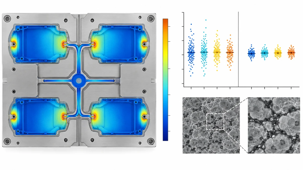
In a multi-cavity mold, the melt travels from the sprue through successive runners into individual cavities and encounters different flow lengths, turns and cross-section changes. Every cavity therefore receives a different shear and thermal history. These differences alter the distribution density and morphology of the antistatic phase in each cavity, ultimately appearing as significant cavity-to-cavity resistance scatter.
The physical mechanism is more specific than a simple material-batch variation. Different areas of one molded part can differ by one or two orders of magnitude, and weld lines can interrupt the charge-dissipation network and create a locally high-resistance area. The direction of the gate-to-end difference is process dependent: phase concentration can make the gate area lower in resistance in one system, while strong gate shear and frozen orientation can make it higher in another. That is why the actual molded resistance map, not a universal gate rule, must decide acceptance.
Antistatic PP is a multiphase composite. The resin matrix and functional phase differ in thermal stability, flow behavior and dispersion response. Under injection shear, the functional phase can orient, migrate or deform. If the mold is too cold and the skin freezes too quickly, the phase remains locked in a flow-oriented state, network connectivity falls, and resistance rises with pronounced anisotropy. Temperature differences between cavities amplify the effect.
2. Material-side route: the formulation logic of KJD789R-A1
The core design of DGK-PP KJD789R-A1 for multi-cavity molding is to retain the PP matrix's processing capability while building an antistatic network with greater tolerance to shear and temperature fluctuation.
Its melt flow rate is 7 g/10 min at 230°C/2.16 kg, placing it in the medium-flow injection-molding range for PP and balancing filling ability with melt strength. Within a 195–210°C barrel window and around 70°C mold temperature, the material can maintain stable flow behavior during filling. This avoids excessive migration of the antistatic phase when viscosity is too low and incomplete filling of remote cavities when viscosity is too high.
For mechanical performance, a flexural modulus of 1790 MPa is in the medium-to-upper range for a PP matrix and supports the rigidity required by trays and circulation boxes. Charpy unnotched impact strength of 40 kJ/m² and Izod notched impact strength of 7.2 kJ/m² provide demolding strength for thin-wall multi-cavity parts. A heat-deflection temperature of 93°C at 0.45 MPa covers ordinary electronics-manufacturing and warehousing conditions.
The resistance of antistatic PP cannot be locked by formulation alone. Values in a material data sheet are references measured on standard molded specimens. The actual distribution among cavities depends on how sensitive the formulation is to the molding process. The purpose of KJD789R-A1 is to keep that process sensitivity within an acceptable project window.
3. Process-side route: control from drying through demolding
Resistance uniformity in multi-cavity molding requires process control as much as material formulation.
Drying
The recommended drying condition for KJD789R-A1 is 85°C for 4–5 hours. PP itself has low moisture absorption, but functional components in an antistatic formulation can be moisture sensitive. Trace moisture can vaporize in the hot melt and create microscopic voids at the interface between the antistatic phase and matrix, interrupting charge paths and raising local resistance. Strict drying is the first control point for cavity and batch consistency.
Temperature window
A 195–210°C barrel range is a conventional PP processing window. Excessive temperature can degrade PP, reduce melt viscosity and weaken the shear needed for uniform dispersion; insufficient temperature makes the melt too viscous and compromises remote-cavity filling. A 70°C mold is relatively warm for PP and gives the oriented functional phase time to rebuild connected charge paths after filling. For the case below, a 70–80°C mold window was used during process optimization.
Multi-cavity filling balance
Filling balance is the most important variable in a multi-cavity tool. An unbalanced system leaves some cavities underfilled and others overpacked, directly changing the final state of the antistatic phase. During the first trial, measure surface resistance at defined positions in every cavity and confirm that all cavities remain in the same agreed order-of-magnitude window. If one cavity reads abnormally high, first inspect its fill completion, runner restriction, venting and local mold temperature.
Demolding and post-treatment
Do not use a mold-release agent. An insulating film on the surface can directly shield the antistatic response, create a falsely high resistance reading and increase differences between cavities when the film is uneven.
4. Commercial validation: multi-cavity SMT antistatic trays
An SMT contract manufacturer in East China used DGK-PP KJD789R-A1 to produce 1.8 mm-wall antistatic SMT trays in a four-cavity mold. The trays circulate through an automated component line and repeatedly contact grippers and conveyors; in a dry season, uncontrolled static charge can reach several thousand volts.
During trial validation, five surface-resistance points were measured on trays from every cavity. Resistance near the gate measured 1.5 × 10¹⁰ Ω, while the average at the four remote corners was 4.2 × 10⁹ Ω. The gate area was about half an order of magnitude higher, and the overall coefficient of variation was approximately 28%.
This measured direction is consistent with this molding setup: shear is strongest near the gate, the functional phase is more highly oriented, and the cooled network has relatively lower connectivity, so gate resistance is higher than at the remote points. For this specific four-cavity thin-wall tray program, the customer accepted an overall CV below 30%; this should not be treated as a universal limit for every product.
For environmental stability, resistance increased from 3.8 × 10⁹ Ω to 8.5 × 10⁹ Ω after 48 hours at 12% RH and remained in the same order of magnitude. After 50 alcohol wipes, it increased from 4.1 × 10⁹ Ω to 5.6 × 10⁹ Ω, a drift of about 0.15 order of magnitude. These results show limited humidity and wiping sensitivity under the stated test conditions, rather than proving complete independence from every environment.
For batch consistency, five parts were sampled from each of three consecutive batches. The batch-average resistances were 3.5 × 10⁹ Ω, 4.2 × 10⁹ Ω and 3.8 × 10⁹ Ω, while within-batch CV values were 18%, 22% and 20%. The batches remained in the same order-of-magnitude window and met the SMT tray project's stability requirement.
The process was locked at a 195–210°C barrel window, 70–80°C mold temperature and medium-to-low injection speed. The gate section was enlarged appropriately to reduce shear damage to the antistatic phase, and each cavity was checked for balanced filling so that an underfilled cavity could not create an abnormal resistance result.
5. Core logic of the technical route
DEYU's route for resistance uniformity in multi-cavity antistatic PP can be summarized as material-side sensitivity reduction plus process-side variable control.
The material objective is not the lowest resistance at one test point. It is an antistatic network that tolerates reasonable shear and temperature variation. KJD789R-A1's 7 g/10 min MFR and 1790 MPa flexural modulus balance filling capability, melt stability and finished-part rigidity. The process objective is not to copy a fixed parameter set blindly, but to establish controls for drying, temperature, filling balance and demolding around preservation of the antistatic network.
For every multi-cavity program, measure each cavity independently during trial molding and establish its resistance-distribution baseline. During production, periodically sample the same cavity positions and monitor them for directional drift. This approach detects an emerging filling imbalance earlier than a single overall resistance measurement and ties material approval to the actual mold, conditioning and test method.